CHAPTER 9
94 RCM - Sprayer and AIM Command FLEX™ II Calibration and Operation Manual
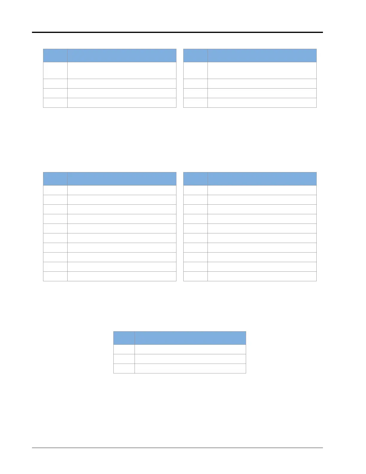
TABLE 4.
NCV Cable Connector Pins
TROUBLESHOOTING 19-PIN BOOM CABLE CONNECTIONS
Boom connection cables alternate NCV power and ground circuits within the cable for banks of NCVs. Adjacent
NCVs may not necessarily not be on the same HC power and ground circuit. Look at the end of the plug to locate
the pin numbers.
TABLE 5.
Boom Cable Connection Pins
TROUBLESHOOTING TERMINATOR CONNECTIONS NEAR THE RCM
Terminator connection referenced from cable side.
TABLE 6.
Terminator Connection Pins
Pin Description Pin Description
1
Aux Device Output (High Flow
Cables Only)
5
Aux Device Input (High Flow Cables
Only)
2 CAN Lo Out 6 Chassis Power (12 VDC Nominal)
3 CAN Hi Out 7 CAN Hi In
4 Chassis Ground (0 VDC) 8 CAN Lo In
Pin Description Pin Description
1- 11-
2 - 12 HC Circuit 2 Power
3 CAN Hi Return 13 -
4 CAN Lo 14 HC Circuit 2 Ground
5- 15-
6 CAN Hi 16 HC Circuit 3 Power
7 CAN Lo Return 17 Fence Row
8 HC Circuit 1 Power 18 HC Circuit 3 Ground
9- 19-
10 HC Circuit 1 Ground
Pin Description
ACAN Hi
BCAN Lo
C-