APPENDIX C
116 RCM - Sprayer and AIM Command FLEX™ II Calibration and Operation Manual
NOZZLE CONTROL VALVE MAINTENANCE PROCEDURE
AIM Command FLEX™ II nozzle control valves are designed to provide maintenance free operation with proper
equipment maintenance as recommended by the equipment or chemical manufacturer. However, the seals may
become worn or swollen due to chemical compounds, chemical formulations, or high operating pressures. This
may cause accelerated wear to the sealing surfaces. The following nozzle control valve maintenance procedures
should be performed on the nozzle control system or on individual NCVs if leaks are observed at a specific spray
tip.
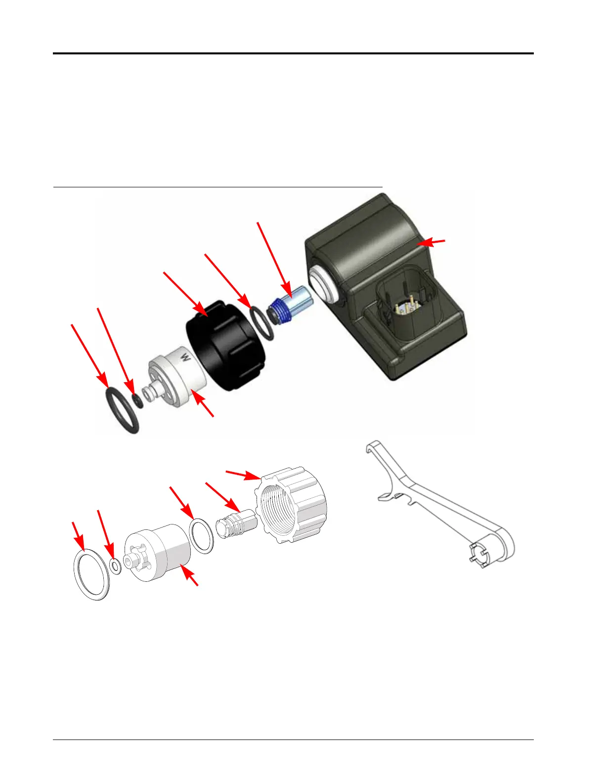
FIGURE 2. Nozzle Control Valve Maintenance Detail
1. Loosen the fly nut (item 1) and remove the AIM Command FLEX™ II nozzle control valve from the nozzle body.
2. Inspect the large o-ring (item 6) on the face of the valve body (item 4). Replace if necessary.
3. Inspect the small o-ring (item 5) on the tip of the valve body. Replace if necessary.
4. Using a valve body removal tool (P/N 321-0000-490), loosen and remove the valve body (item 4) from the AIM
Command FLEX™ II nozzle control valve.
1
2
3
4
5
6
Nozzle
Control Valve
1
2
3
4
5
6
Valve Body Removal Tool
(P/N 321-0000-490)