APPENDIX A
102 RCM - Sprayer and AIM Command FLEX™ II Calibration and Operation Manual
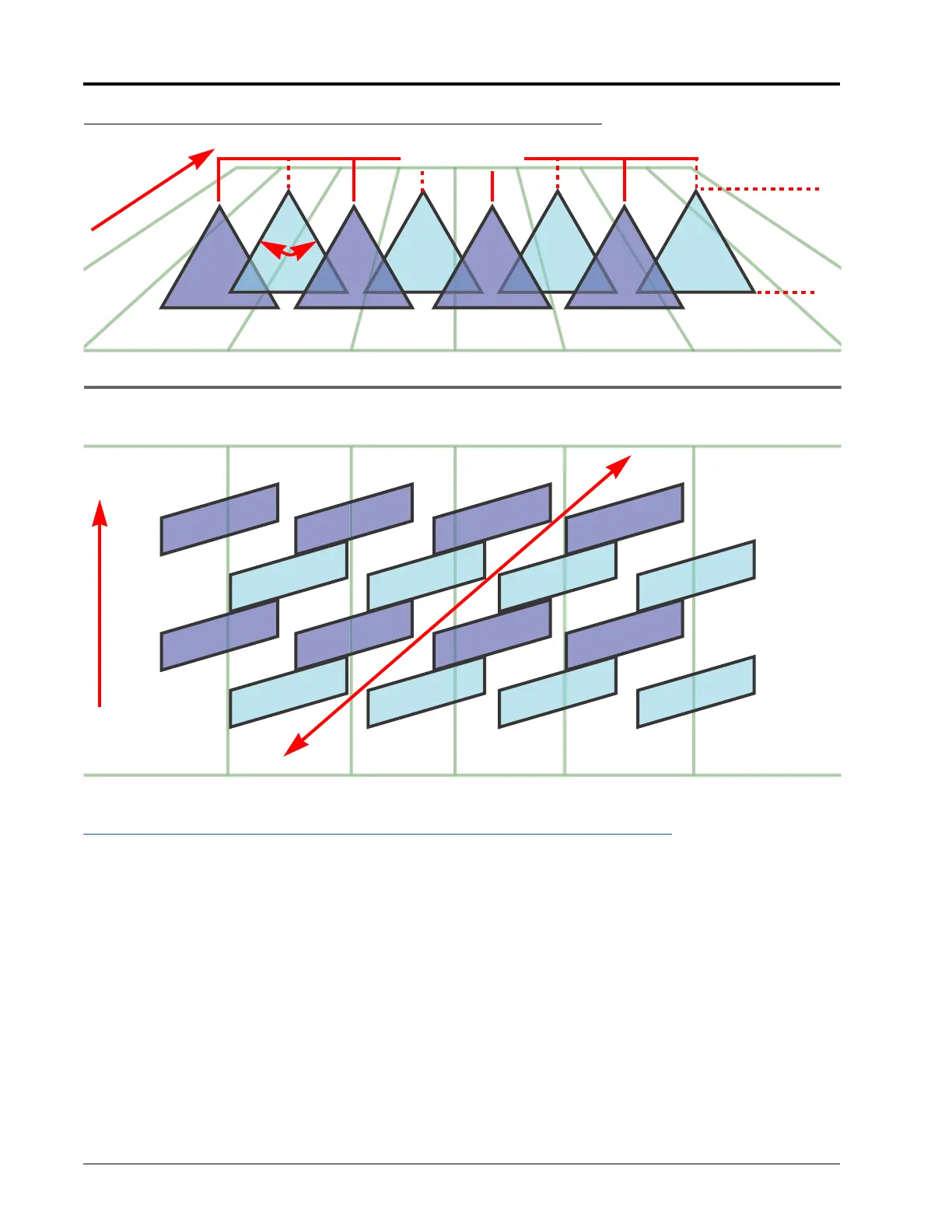
FIGURE 3. Conditions Resulting in Under Application and Diagonal Banding
TIP SELECTION AND APPLICATION SPEED GUIDE
DROPLET SIZING
The table below shows the droplet size specifications for different spray tip manufacturers. Use this information
when selecting the appropriate spray tips for your application.
To properly size spray tip and type, determine the typical spray speed, target pressure desired for droplet size, and
target rate for application.
NOTE: The following tables are common examples. Please refer to the latest spray tip information available
from the tip manufacturer for specific applications, compatibility with PWM control technology, and
droplet size information.
Tip Spacing
20 inch [50.8 cm]
80°
Spray Tip
Height
21 inch
[53.3 cm]
Alternating Spray Pattern
Alternating Spray Tip Pattern
Coverage View from Above
Diagonal Banding
Direction of
Travel
V
e
h
i
c
l
e
T
r
a
v
e
l
1
5
M
P
H
[
2
4
.
1
k
p
h
]