CHAPTER 4
28 RCM - Sprayer and AIM Command FLEX™ II Calibration and Operation Manual
CONTROL VALVE PWM SETUP
The PWM Setup page allows the operator to tune PWM control and system response for the specific application
system.
Coil Frequency. The default coil frequency is 50 Hz. Set the frequency of the PWM valve coil. Refer to the PWM
control valve manufacturer specifications for the recommended PWM frequency.
PWM High Limit. Set the maximum desired output for a pump controlled by a pulse width modulated (PWM)
hydraulic control valve. This setting limits how far the PWM valve will open.
With the machine section and master switches in the on position, increase this value until the maximum desired
pressure is reached in a liquid system.
NOTE: The maximum operating pressure of the AIM Command FLEX™ II NCVs is 105 psi [724 kPa]. Adjusting
the PWM high limit beyond the maximum response point of the valve will significantly reduce the
expected service life of NCVs on the system and result in control response delays at the upper end of
the system capacity range.
PWM Low Limit. Set the minimum desired output (zero point or shutoff point) for a pump controlled by a pulse
width modulated (PWM) hydraulic control valve.
NOTE: Adjusting the PWM low limit below the minimum response point of the valve will result in control
response delays at the low end of the system capacity range.
PWM High Side Drive. When enabled, this feature allows the system to modulate the high side (+) of the driver
while providing a constant ground return. Most commonly used when a PWM boost box is installed.
MINIMUM NCV PWM
NOTE: Minimum NCV PWM is not available when operating in the Bypass NCV control mode.
Enter a minimum PWM percent to set the minimum desired output (zero point or shutoff point) for the AIM
Command FLEX™ II nozzle control valves.
With the machine master switch in the on position, decrease this value until the minimum desired spray pattern is
reached in the liquid system.
NOTE: To help avoid under application or skips in coverage, review Appendix A, Avoiding Skips with AIM
Command FLEX™ II Nozzle Control System, and maintain the recommended application conditions.
CAUTION
Operating at an insufficient NCV PWM may
result in under application or skips in coverage.
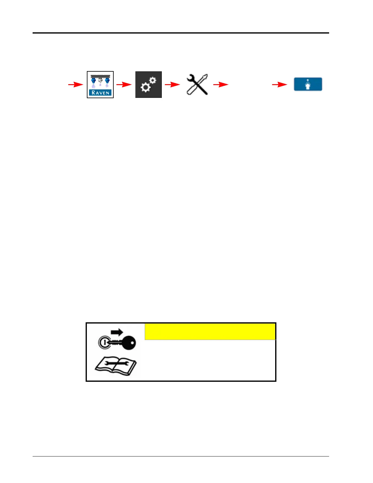
RCM - Sprayer Menu Tools Menu System
Settings
UT Menu
Control Valve
Setup
PWM
Setup