Wuhan Raycus Fiber Laser Technologies Co., Ltd.
User Guide of RFL-C20000TZ
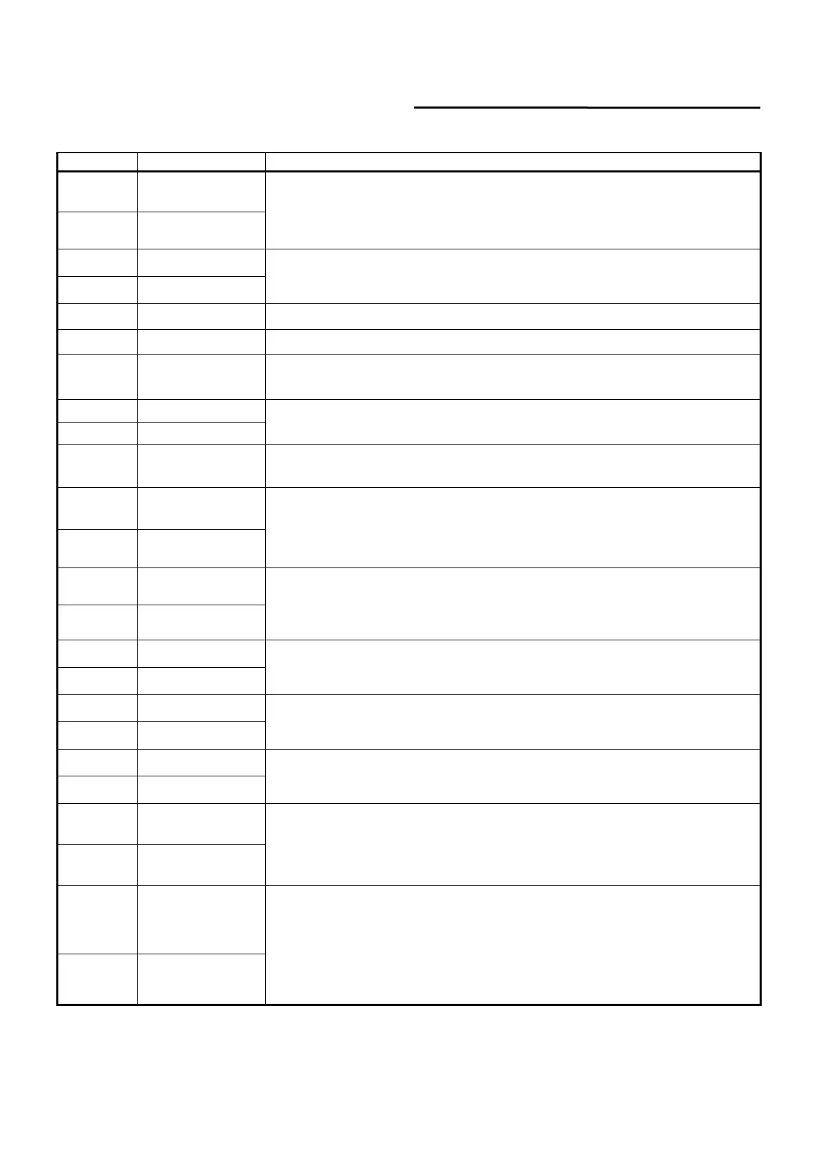
Table 6 XP2 security interface definition
Output control, differential voltage input signal;
laser ON: 4V~30V; laser OFF: -3V~2V;
Maximum modulation frequency: 5kHz(4kW~12 kW); 2kHz(15kW~20kW).
Laser output indication, MOS pipe D, S output;
current<0.1A, V
DS
<60V, passive signal.
Connect the negative pole of the external laser-emitting indicator, current<100mA
Connect the negative pole of the external power-on indicator, current<100mA
Connect the positive pole of the external laser-emitting indicator;
active signal, current<400mA
On REM mode, the main control board is powered on when pin-8 and pin-9 are
closed; 24V active contact output, no external voltage or grounding.
Connect the positive pole of the external power-on indicator;
active signal, current<400mA
Emergency output 1 on the front panel, relay output contact, passive contact,
current <100mA, voltage<30V;
If the current panel stop pressed, pin-11 and pin-14 are open, or else close.
Emergency output 2 on the front panel, relay output contact, passive contact,
current <100mA, voltage<30V;
If the current panel stop pressed, pin-12 and pin-13are open, or else close.
Main power supply power on output indication, MOS pipe D, S output
current<0.1A,V
DS
<60V, passive signal.
Interlock1 input, the pin-17 and pin-20 should be closed normally;
active contacts, no external voltage or grounding.
Interlock2 input, the pin-18 and pin-19 should be closed normally;
active contacts, no external voltage or grounding.
Close the pin-21 and pin-22 to start the main power supply remotely.
(The function is the same as the LASER button on the front panel.)
active contacts, no external voltage or grounding.
Pin-23 and pin-24 indicate the laser key switch status:
Opened - the laser key switch is in the OFF position;
Closed - The laser key switch is in the ON or REM position.
Passive contact, external voltage signal, the voltage is less than 30V, and the
current is less than 1A.
 Loading...