Wuhan Raycus Fiber Laser Technologies Co., Ltd.
User Guide of RFL-C20000TZ
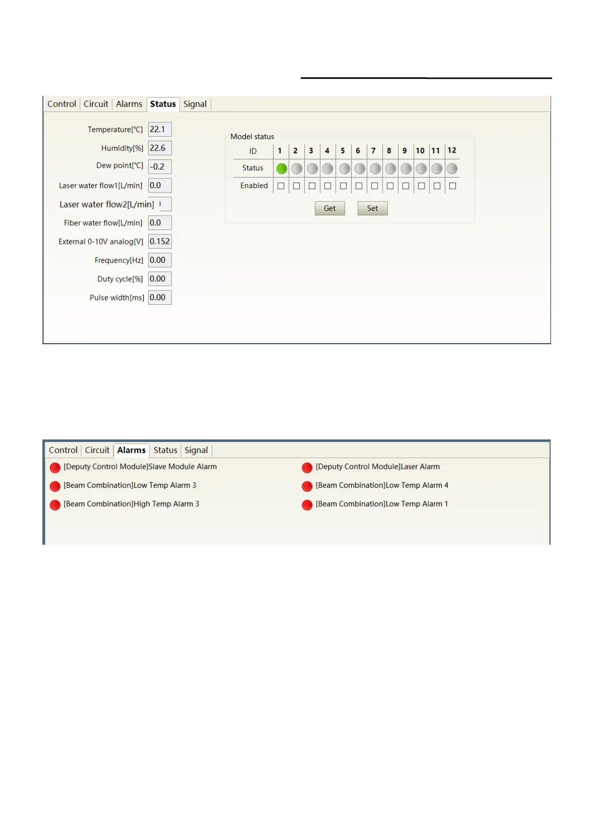
Figure 39 Laser parameter display area display interface
8.5 Alarm Type Display Area
The laser alarm type display area interface is as Figure 40. This interface shows the cause of the
alarm for the current laser.
Figure 40 Laser alarm type display area interface
8.6 PC Software Operating Mode Selection
The laser operating mode is set by the PC software. Its operating interface is as Figure 41. The
interpretation of the various patterns can be found in Table 16. The programming editing interface is
displayed on the software only when programming mode is selected.
 Loading...