EasyManuals Logo
Home>Raycus>Measuring Instruments>XZ Series

Raycus XZ Series User Manual

Raycus XZ Series
80 pages
To Next Page IconTo Next Page
To Previous Page IconTo Previous Page
Page #50 background imageLoading...
Page #50 background image
Wuhan Raycus Fiber Laser Technologies Co., Ltd.
User Guide of RFL-C20000TZ
46
6.5 Set the Power Analog Quantity in REM Mode to Control the Laser Emission
XP1(Hardwiring)
AC INPUT
XP2
(Security Interface)
AC POWER
~380VAC
L1
L2
L3
PE
1
2
8
9
17
18
19
20
A16(COM)
Interlock1
Interlock2
A1(Laser Request)
Raycus Laser
MOD+
MOD -
Peripheral
Equipment
XP4(Analog Interface)
Analog value(0~10V)
Analog GND
A2(Laser EN)
A6(Analog EN)
Power ON
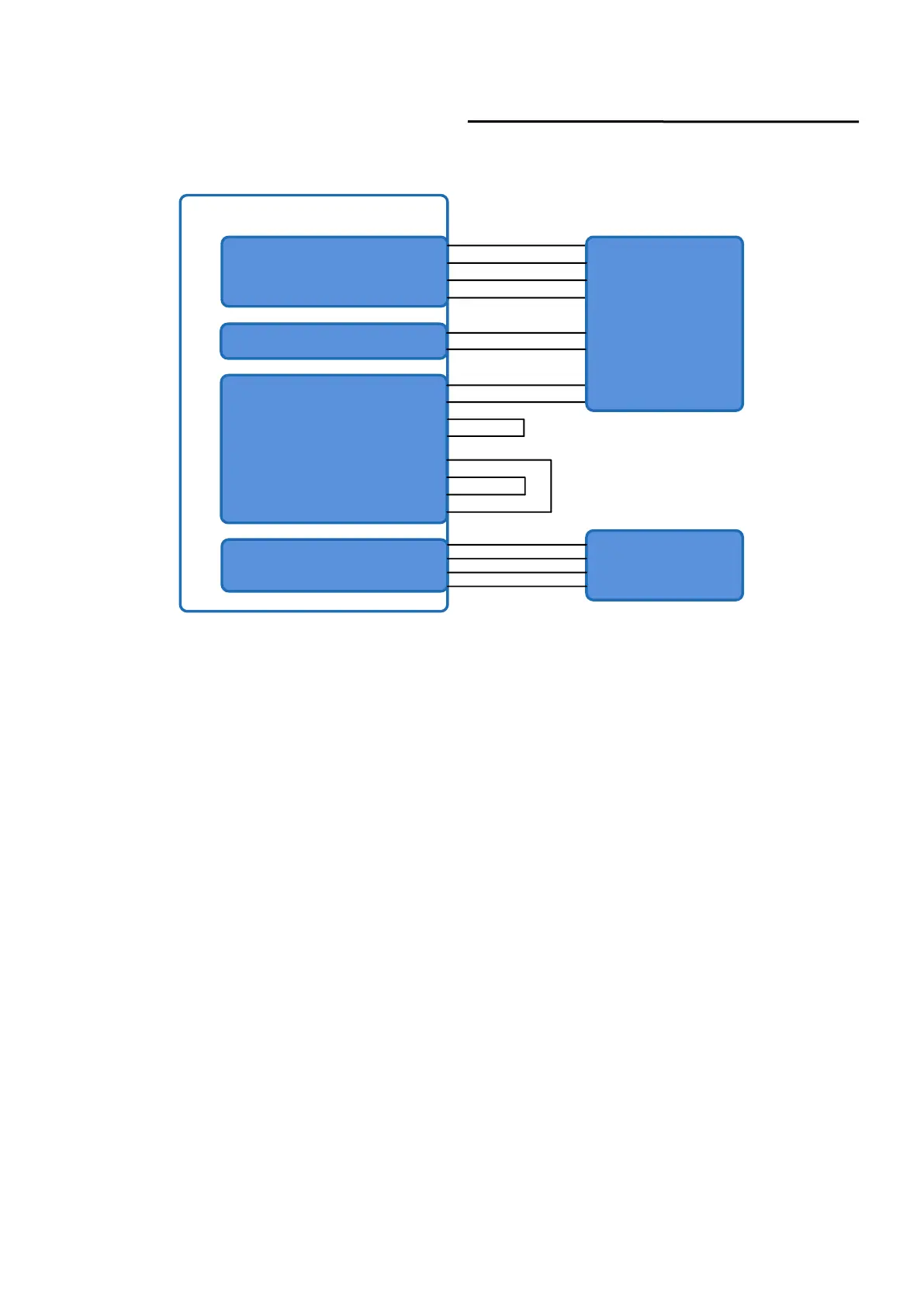
Figure 22 REM mode power and laser emission are externally controlled wiring diagram
Operations Steps
a) Turn the knob switch on the rear panel to“ON”
b) Turn the key switch to“REM”
c) Short-circuit pin 8/9 on XP2
d) XP1-A1 connects to 24V, XP1-A6 connects to 24V
e) Connect XP1-A5 to 24V and turn on the guide laser; after checking the optics, connect XP1-A5
to 0V and turn off the guide laser
f) XP1-C1 is connected to 24V, and the main power is turned on (operator can also directly press
the LASER button, or clicks the main power “ON” on the Raycus PC software)
g) Waiting for “Ready
h) XP1-A2 connects to 24V, and the control board outputs analog and MOD signals

Table of Contents

Questions and Answers:

Question and Answer IconNeed help?

Do you have a question about the Raycus XZ Series and is the answer not in the manual?

Raycus XZ Series Specifications

General IconGeneral
BrandRaycus
ModelXZ Series
CategoryMeasuring Instruments
LanguageEnglish

Related product manuals