4.5 Introduction to Safety Interlock
Raycus’ product is designed with a safe interlocking loop, which is a two-channel system with
output monitoring and manual reset. When the safety interlocking circuit is open, the safety circuit will
disconnect the working power of the optical module, that is, the main power supply of the optical module.
To start the main power supply, you must close the two interlocking channels (24 pin interface: short 17
and 20, short 18 and 19). Otherwise, the main power will be turned off and the laser can not be turned on
at this time. When one of the channels is open, the laser main power supply is impossible to start until the
other channel is open, and then the two channels are closed before the laser main power supply can be
started.
If the interlock is closed (the stop button is also released) and there is no error alarm, press the start
(LASER) button to start the main power supply, and “the main power has been started” pin of the external
interface(XP1-B8) will have a high-level output. When the security interlocking circuit is open or the
error is detected, the main power supply of the optical module will be turned off, and the B8 of XP1
interface will become low level. The detected “error state” is latched and the on-board relay opens the
manual reset loop with monitoring until the error is cleared, thus preventing the laser from being restarted.
If errors such as short circuit between interlocking channels or short circuit of start (LASER) button are
detected, the safety loop can not be reset before the error is cleared.
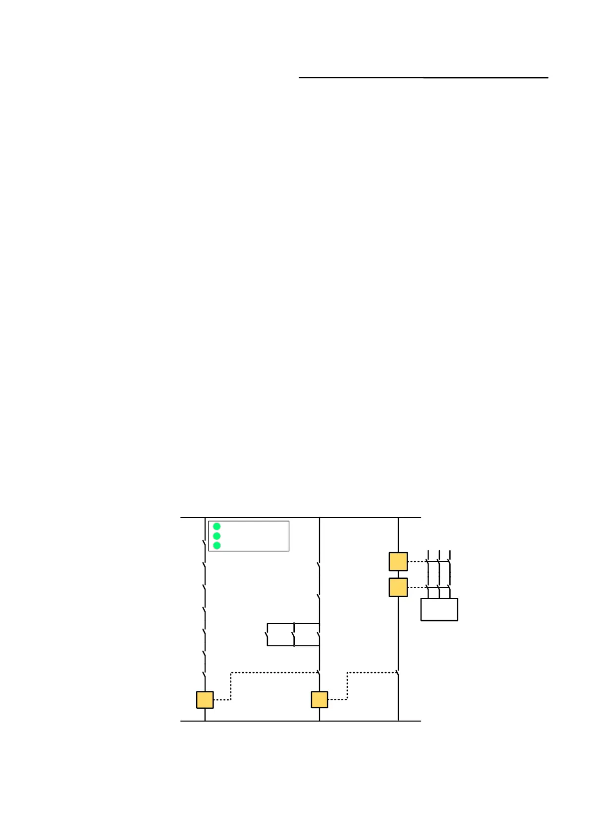
4.6 Schematic Diagram of the Internal Electrical Circuit of the Laser
The internal electrical circuit of the laser is shown in figure 17.
 Loading...