Wuhan Raycus Fiber Laser Technologies Co., Ltd.
User Guide of RFL-C20000TZ
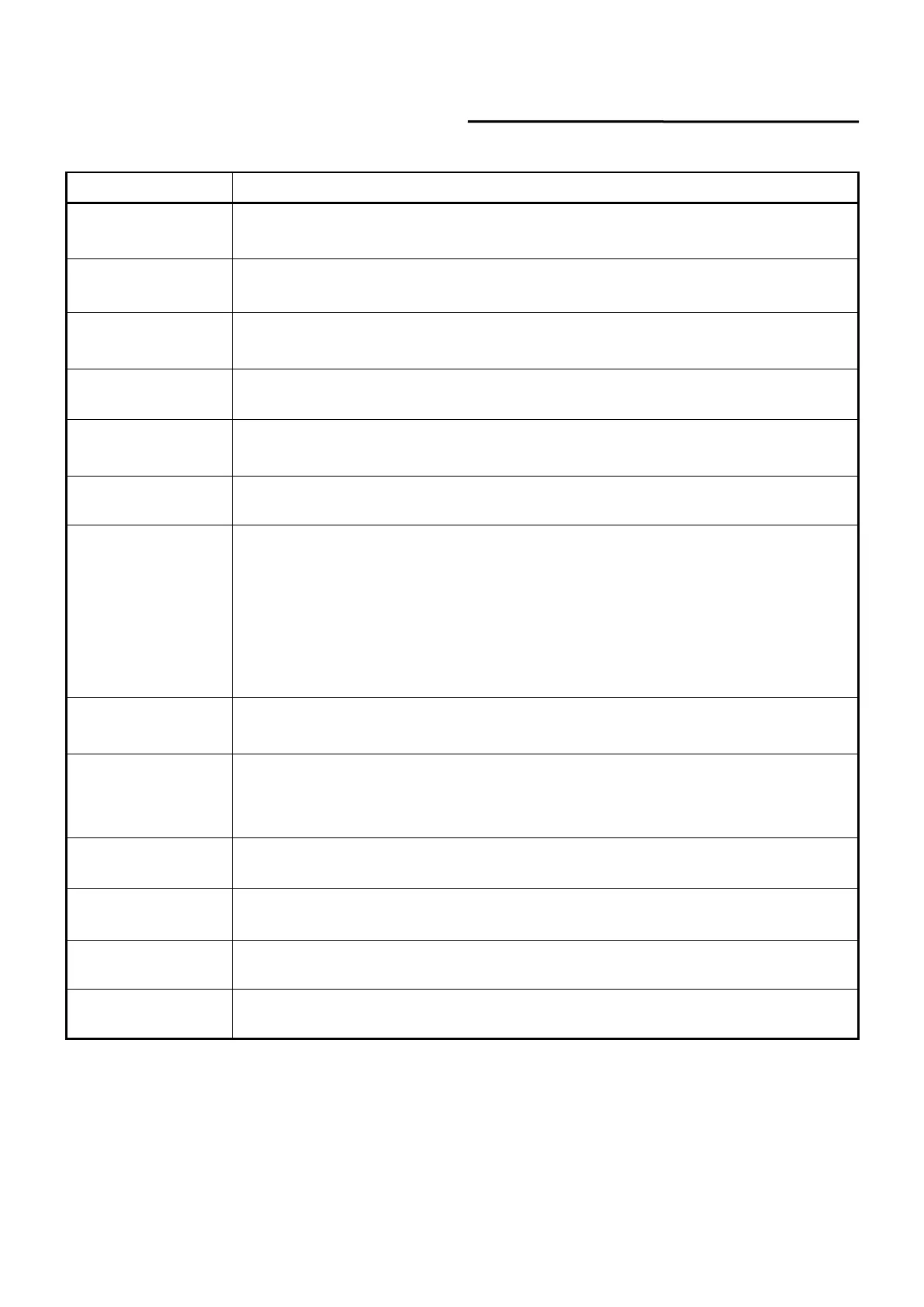
Table 14 The laser main display area meaning
Red: emergency stop button on front panel is pressed;
Gray: emergency stop button is reset.
Green: laser works in REM mode;
Gray: laser works in ON mode.
Guide laser external
control
Green: laser works in red laser external control mode;
Gray: laser works in red laser internal control mode (Guide laser’s on/off is controlled by PC
software).
Green: red laser is on;
Gray: red laser is off.
Green: Interlock spot at output fiber end is closed;
Gray: Interlock spot at output fiber end is opened.
Green: laser works in external control mode;
Gray: laser works in internal control mode (Laser’s on/off is controlled by PC software).
Green: laser operates in power linear correction mode, in which control system automatically
adjusts the laser's output power. It makes the output power linear, with a longer response
time for AD analog in this mode, longer than 1ms;
Gray: laser operates in non-correction mode, and the external 0-10V analog voltage is linear
only with the current of the pump auxiliary tube. The response time for this mode AD
simulation is less than 100us.
Green: laser power is determined by the 0-10V analog voltage on XP4 when laser works in
AD mode;
Gray: laser power is set by PC software or communication commands.
Green: PC software is in monitoring mode. User can monitor laser status only, but not able
to take control of laser. Monitoring model is activated when interface 10001 of laser is
occupied;
Gray: PC software operate in normal mode.
Green: XP2 leg 17,18 on safety interface closed;
Gray: XP2 leg 17,18 on safety interface opened.
Green: XP2 leg 19,20 on safety interface closed;
Gray: XP2 leg 19,20 on safety interface opened.
Green: laser is in program mode;
Gray: laser is not in program mode.
Power slow rise & fall
mode
Green: laser works in power slow rise & fall mode;
Gray: laser does not work in power slow rise & fall mode.
8.3.3 Laser Power-up, Mode Selection, Light-out Control Area
Laser power-up, mode selection, light out control display area is as in Figure 35, the display content
is as in Table 15.
 Loading...