Appendix B: Using the Auxiliary Junction Box B-5
Appendix B: Using
the Auxiliary
Junction Box
Raystar 114 Combined GPS and Differential Beacon
Receiver
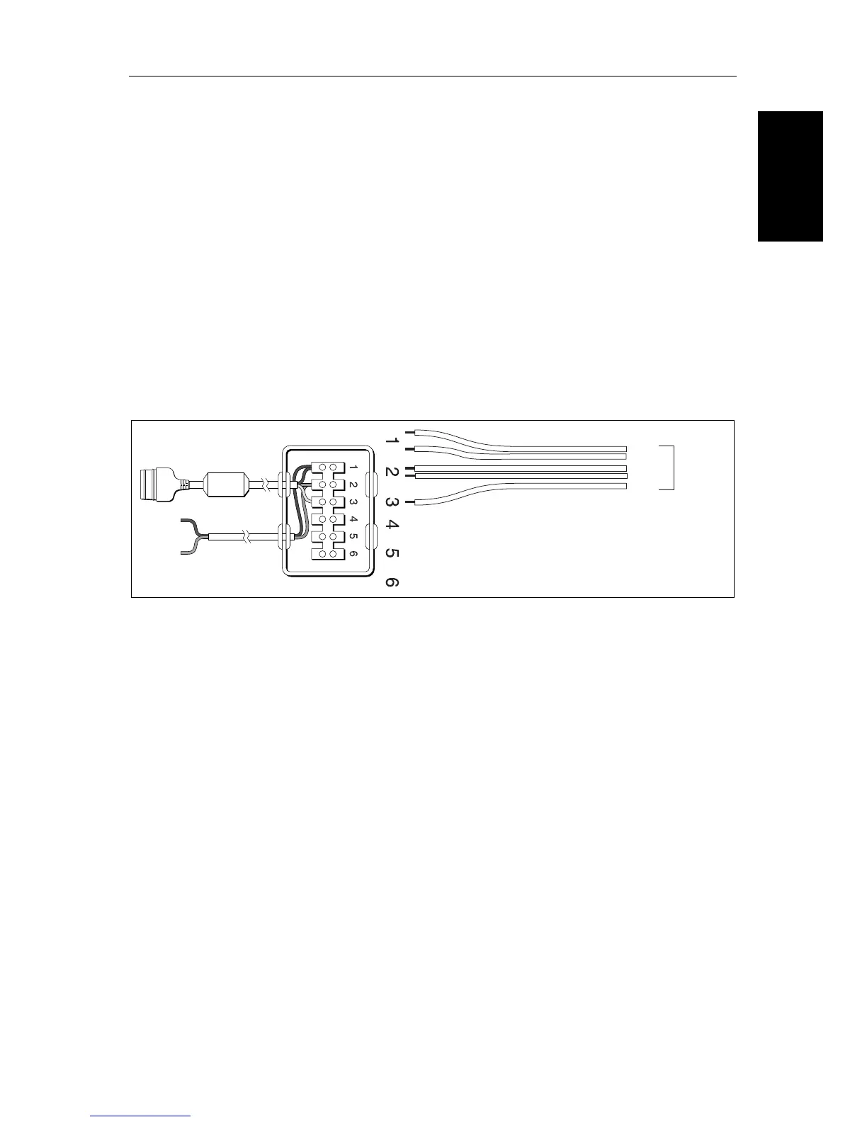
To connect your Raystar 114 Combined GPS and Differential Beacon
Receiver to your Chartplotter or Combined Radar/Chartplotter, cut off the 5-
pin connector, strip back the insulation on all the wires and connect to the
Auxiliary Junction Box as shown in the illustration below.
CAUTION:
Ensure the correct polarity of the 12 V supply before applying display or
SeaTalk power. It is recommended that a multimeter is used to check the
connections.
Note: You can use the GPS Set-Up page to manually tune the Raystar 114. Re-
fer to Chapter 6for details.
12V
Power
Supply
(fused)
From
Combined
GPS/DBR
sensor
Green
Red
Black
To Display Unit
SeaTalk Socket
D4301_1
Red
Black
White
Yellow
 Loading...