154
HSB Series LCD Display
Power and NMEA Input Connection
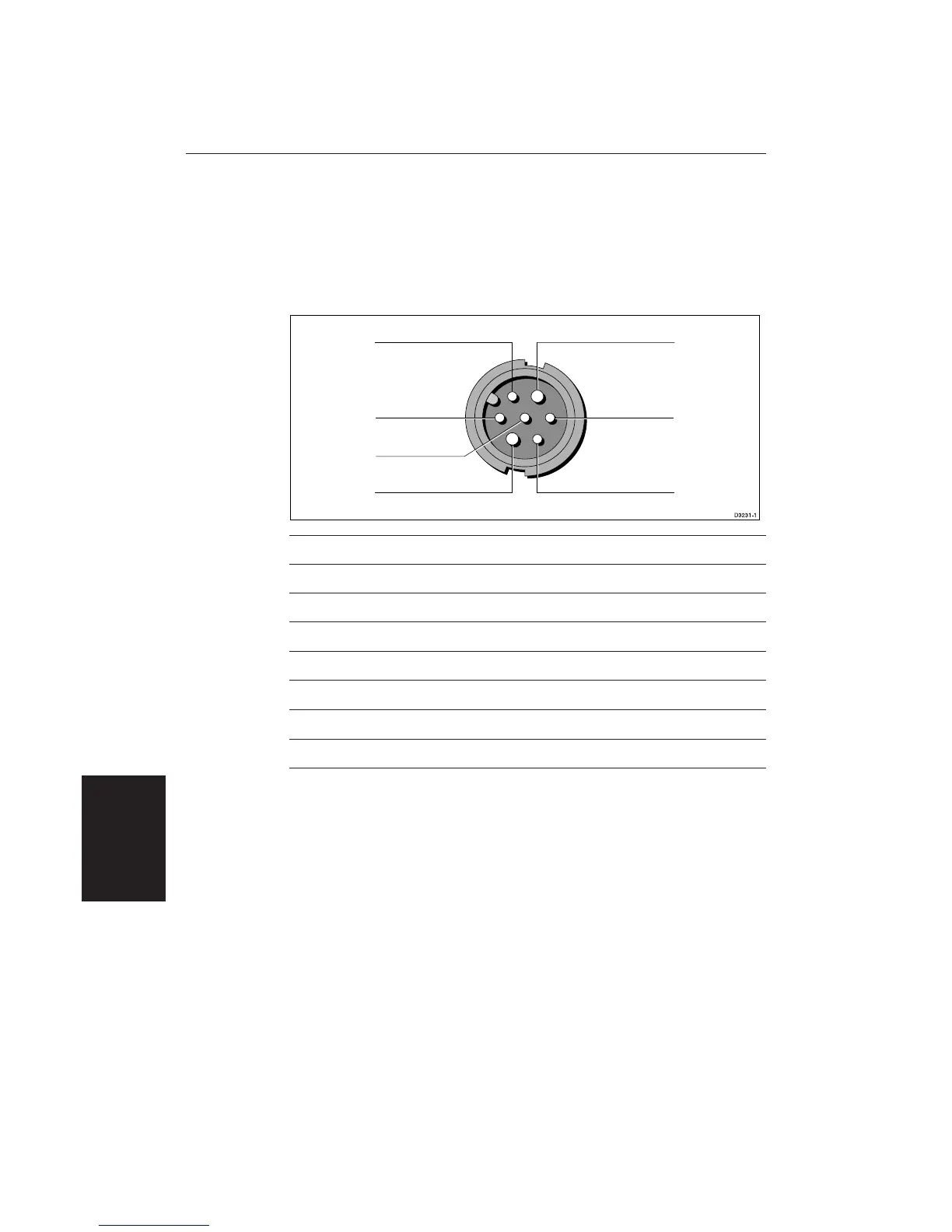
The DC power and NMEA input should be connected at the rear Power/NMEA
seven-pin connector. The connector (viewed from the outside) and pin
functions are shown in the following diagram and table. The NMEA Input is
detailed in Section 8.8 Integrated Systems.
2
1
4
3
5
7
6
Pin No.Pin No.
Pin No.Pin No.
Pin No.
FunctionFunction
FunctionFunction
Function
ColourColour
ColourColour
Colour
1 Channel 1 NMEA data input (+ve) Orange
2 Channel 1 NMEA return (-ve) Yellow
3 Battery negative Black
4 Screen (drain wire) No insulation
5 Battery positive (12/24/32 V systems) Red
6 Channel 2 NMEA data input (+ve) Green
7 Channel 2 NMEA return (-ve) Blue
Power ConnectionPower Connection
Power ConnectionPower Connection
Power Connection
The RED wire must be connected to the feed from the positive (+) battery
terminal and the BLACK wire to the feed from the negative (–) battery
terminal. The shielded wire (screen) should be connected to the ship’s RF
ground as previously described in Grounding the Radar System.
Any unused cores should be insulated and taped back.
CAUTION:
If the power connections are accidentally reversed the system will not
work. Use a multimeter to ensure that the input power leads are connected
for correct polarity.
Switch off the display unit before you remove the power cord.
Display Unit
Connection

 Loading...