Appendix B: Using the Auxiliary Junction Box 185
Raystar 114 Combined GPS and Differential Beacon
Receiver
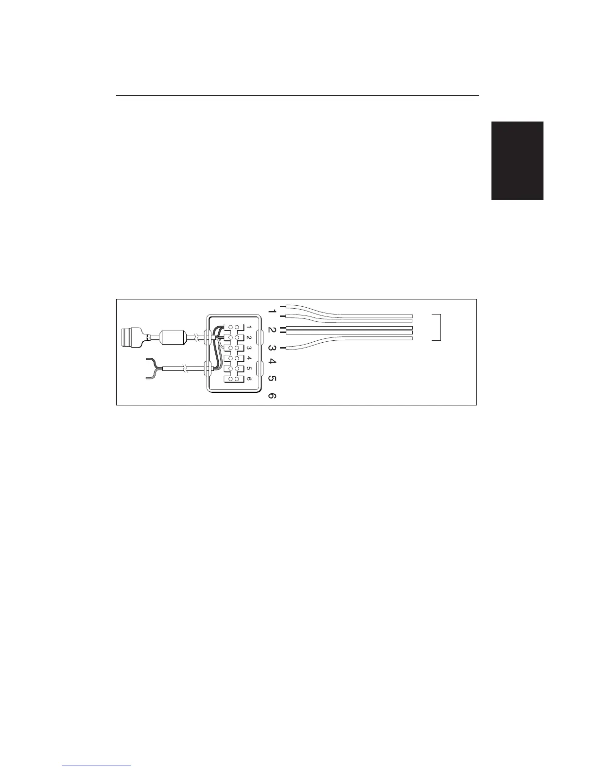
To connect your Raystar 114 Combined GPS and Differential Beacon Receiver
to your Chartplotter or Combined Radar/Chartplotter, cut off the 5-pin
connector, strip back the insulation on all the wires and connect to the Auxiliary
Junction Box as shown in the illustration below.
CAUTION
Ensure the correct polarity of the 12 V supply before applying display or
SeaTalk power. It is recommended that a multimeter is used to check the
connections.
Note: You can use the GPS Set-Up page to manually tune the Raystar 114.
Refer to Chapter 6 for details.
12V
Power
Supply
(fused)
From
Combined
GPS/DBR
sensor
Green
Red
Black
To Display Unit
SeaTalk Socket
D4301_1
Red
Black
White
Yellow
Appendix B:
Using the Auxiliary
Junction Box

 Loading...