158
HSB Series LCD Display
➤ To adjust the radar to eliminate the alignment error:
1. If a visual relative bearing of a target has been determined, as in 2.1 above,
set an EBL to this relative bearing.
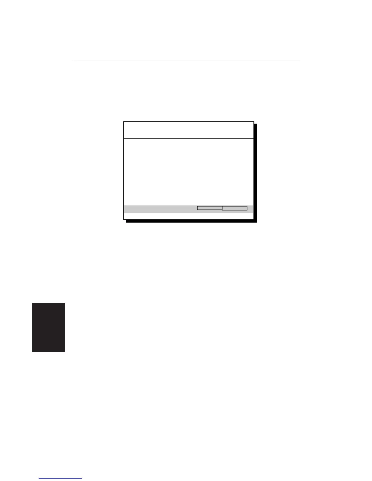
2. Press the MENU key to display the setup soft keys and select RADAR SET
UP.
D3649-2
RADAR SET UP MENU
EBL DISPLAY
TIMED TRANSMIT
TRANSMIT PERIOD
STANDBY PERIOD
DEFAULT MARK SYMBOL
MARK DISPLAY
CLEAR MARKS
CUSTOM SCALE
BEARING ALIGNMENT
RELATIVE
OFF
20 SCANS
10 MINS
x
OFF
OFF
3. Use the trackpad to move the selection bar on the Radar Set Up Menu to
BEARING ALIGNMENT.
4. Use the soft keys to adjust the Bearing Alignment slider and to rotate the
radar picture. As soon as you start the adjustment, the menu is cleared so
that the rotation of the picture can be seen. The keys can pressed and held,
to rotate the picture quickly, rather than in single steps.
5. Rotate the picture to place the target under the EBL, or Heading Marker,
depending on the method used to obtain the correct relative bearing.
6. When the bearing alignment error has been eliminated press ENTER to re-
display the Radar Set Up menu.
7. Press ENTER again to return to the set up soft keys, then press CLEAR to
return to the normal radar screen.
8. After adjusting the radar, always check the bearing alignment at the next
oportunity. Usually the Bow alignment to target (2.2 above) is the most
convenient method.
Display Timing Adjustment
The display timing can be affected by the length of the cable used to connect the
scanner to the display unit. This in turn affects the short range accuracy shown
on the display. If you have extended (or reduced) your inter-unit cable, you will
need to check the display timing before using the system for navigation.
Incorrect timing is most noticeable on the
1
/
8
nm or ¼ nm range scales. Targets
such as bridges or piers appear bent or bowed.
Radar System
Checks and
Adjustments

 Loading...