page 31 of 91 USB-QFLCII-14804/0
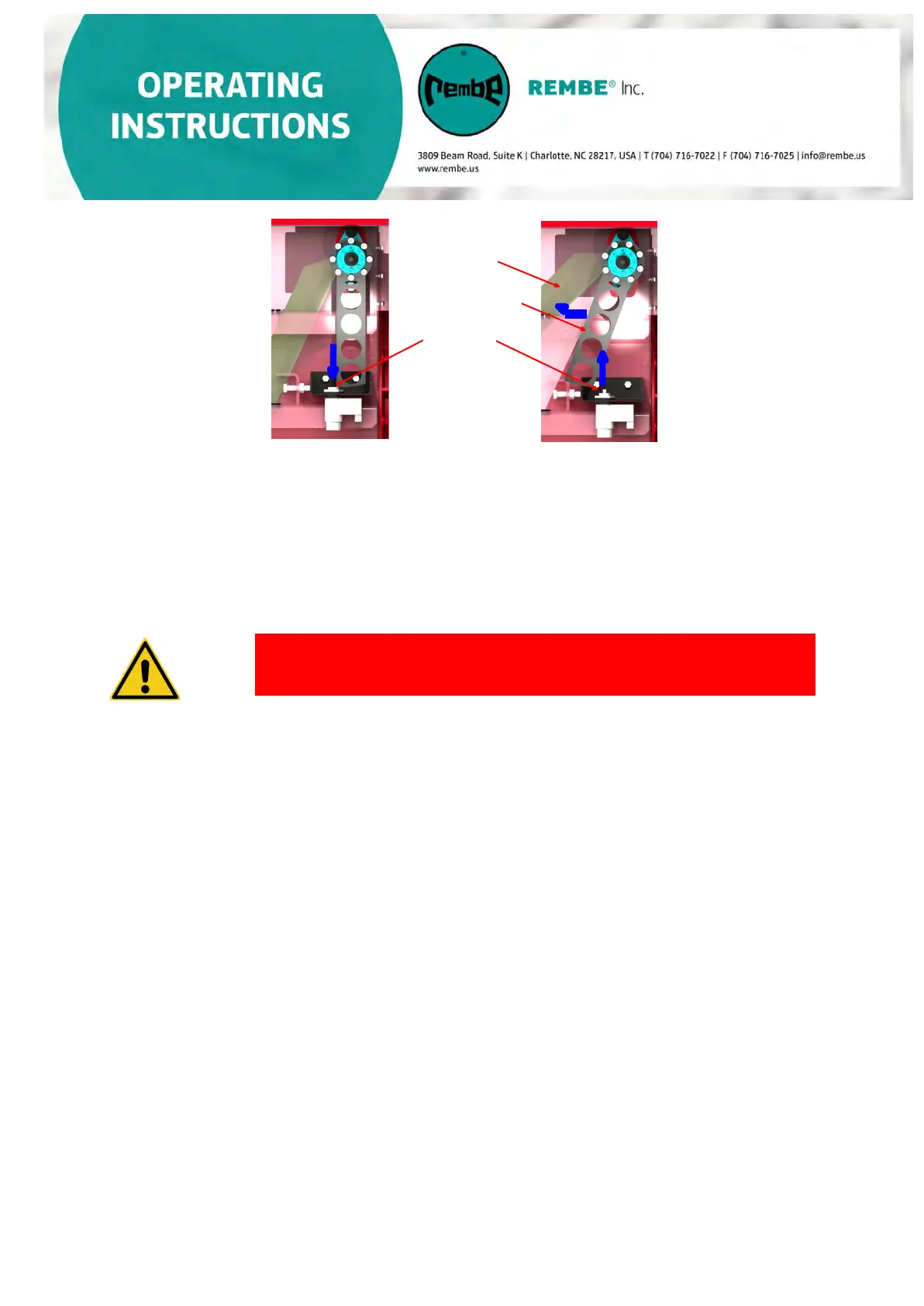
Flap
Locking lever
2.
Locking pin
1.
3.
If the E1 and E2 wire terminals do not switch to “0-signal” (one of the entries does not
switch off), a malfunction is signaled and the system shuts down. Since the electromagnetic
release is still under tension, the locking mechanism would not work.
Locking mechanism technical data:
• Nominal voltage: 24 V
• Effective power: 19.1 W
• Magnetic force: 10.8 N
DANGER
The locking unit’s electromagnetic release should only operate
for a very short period during the start-up process and must not
be “live” during operation.
If the electromagnet is constantly live, this can result in the flap blade not being
locked in the event of an explosion. Should this occur, the inlet isolation device
would not properly isolate the explosion or stop flames from traveling to
upstream system areas!
a) We recommend operating the electromagnet simultaneously with the
fan's starting signal for a duration of 2 seconds (adjustable)
b) For star/delta switch-on or in frequency inverter operation of the fan, it is
necessary to adjust the electromotor’s control time to the system's
start-up behavior during the first commissioning.
-----------------------------------------------------------------------------------------------------
System shutdown/
Locking the unit
When the system is shut down, the flap blade slowly closes by its own weight due to
the
decreasing air flow. During this closing process, the locking lever is “led” over the
locking unit's locking pin. The locking pin is thus pushed downwards against the
spring force. In the closed position (flap blade closed), the locking lever is behind the
locking pin which is again extended, locking the flap blade closed and thus prevents
the re-opening of the flap blade.
 Loading...