page 61 of 91 USB-QFLCII-14804/0
9.9 Inspect the locking mechanism
Ensure that the system is disconnected safely.
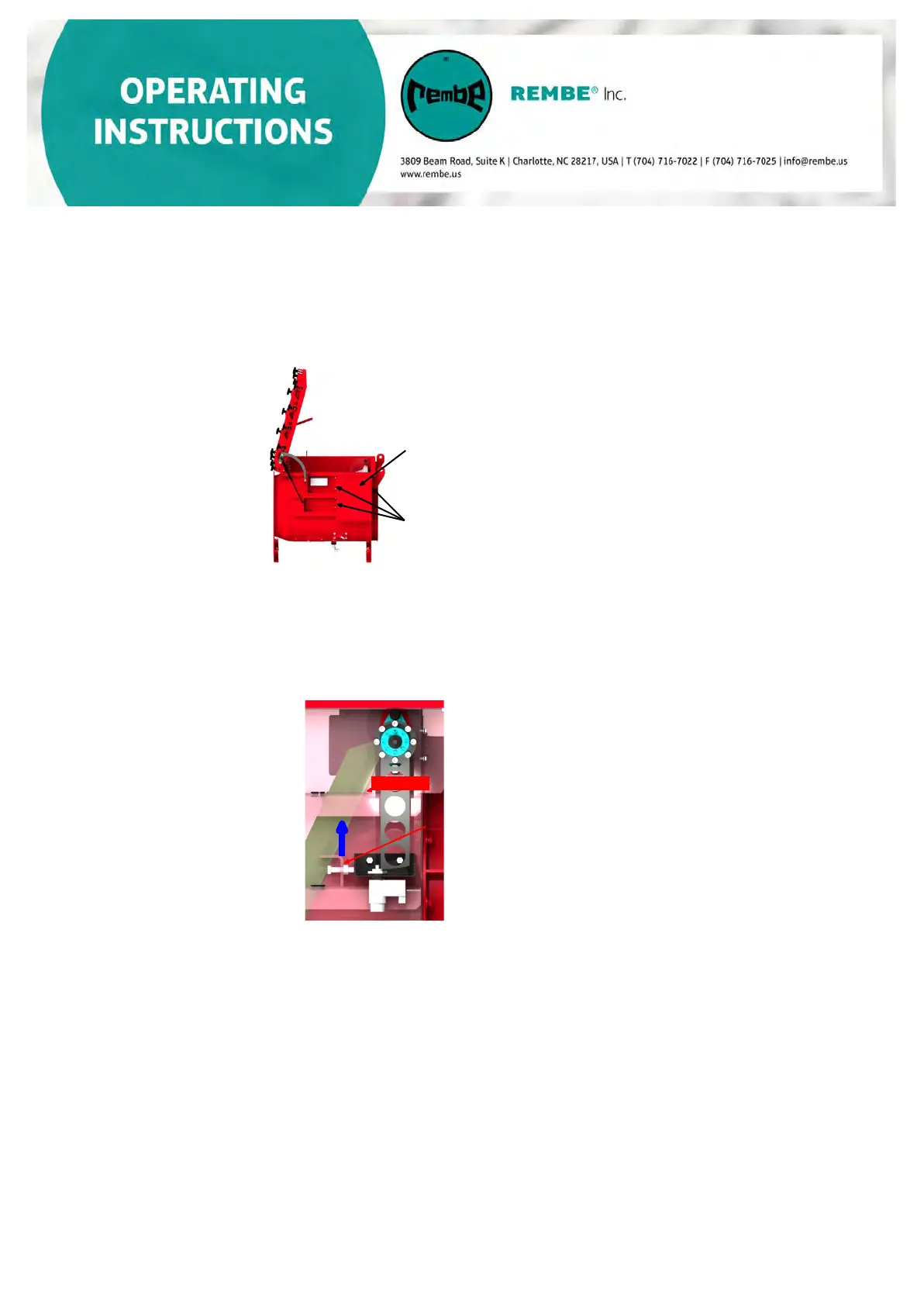
a) Remove the locking mechanism cover which is attached to the inlet isolation
device. All screws must be loosened and removed to remove the cover.
Cover of the
locking
Fixing bolts
b) Check to confirm the flap blade is locked in the proper “disconnected” condition.
The locking lever should be in the position as shown below and the locking pin
should be extended in closed condition. If it is not possible to lock the flap
blade in the closed condition, the locking mechanism needs to be readjusted.
(See Section 9.10 Adjustment of
the locking mechanism )
Locking lever
Locking pin
Visual inspection of the
locking unit
c) Visually inspect the locking mechanism for wear.
•
I
nspect the locking unit/locking pin for wear. In the event of visible
cracks, indentation or severe wear, replace the locking unit.
• Inspect the locking lever. in the event of visible cracks, indentation or
severe wear, replace the locking lever.
d) To ensure the flap blade is securely locked after an explosion, there
should be a distance of approximately 1 mm (0.039 inches) between the
locking lever and locking unit.
• Proceed as described above.
•
Check if enough space between locking unit and locking lever is
available-approximately 1 mm (0.039 inches
)
• If there is a considerably larger distance, the locking unit must be readjusted (see
Section 9.10 Adjustment of the locking unit).
• If the distance is not larger than 1 mm (0.039 inches) please conduct the following
locking mechanism test.
 Loading...