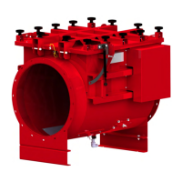
page 43 of 91 USB-QFLCII-14804/0
6.2 Installation conditions
The inlet isolation device should be transported to the place of installation.
a) Loosen the tensioning belts and remove the shrink-wrapping/other packing materials.
b) Unload the inlet isolation device with a crane and suitable lifting
accessories from the pallet.
WARNING
There is danger of physical harm to personnel near the inlet
isolation device if the device is not properly secured to equipment
having sufficient load capacity to transport the device.
Death or
serious injury can result if the inlet isolation device crashes!
Please take into account adequate load-carrying capacity!
Fasten the lifting equipment to the following points:
• Eyebolts that are screwed to the connecting flanges for sizes
up to DN 560. Transport hangers may also be placed around
the pipe connection for sizes up to DN 560.
• Use attached lifting lugs for sizes DN 630 and larger.
--------------------------------------------------------------------------------------------
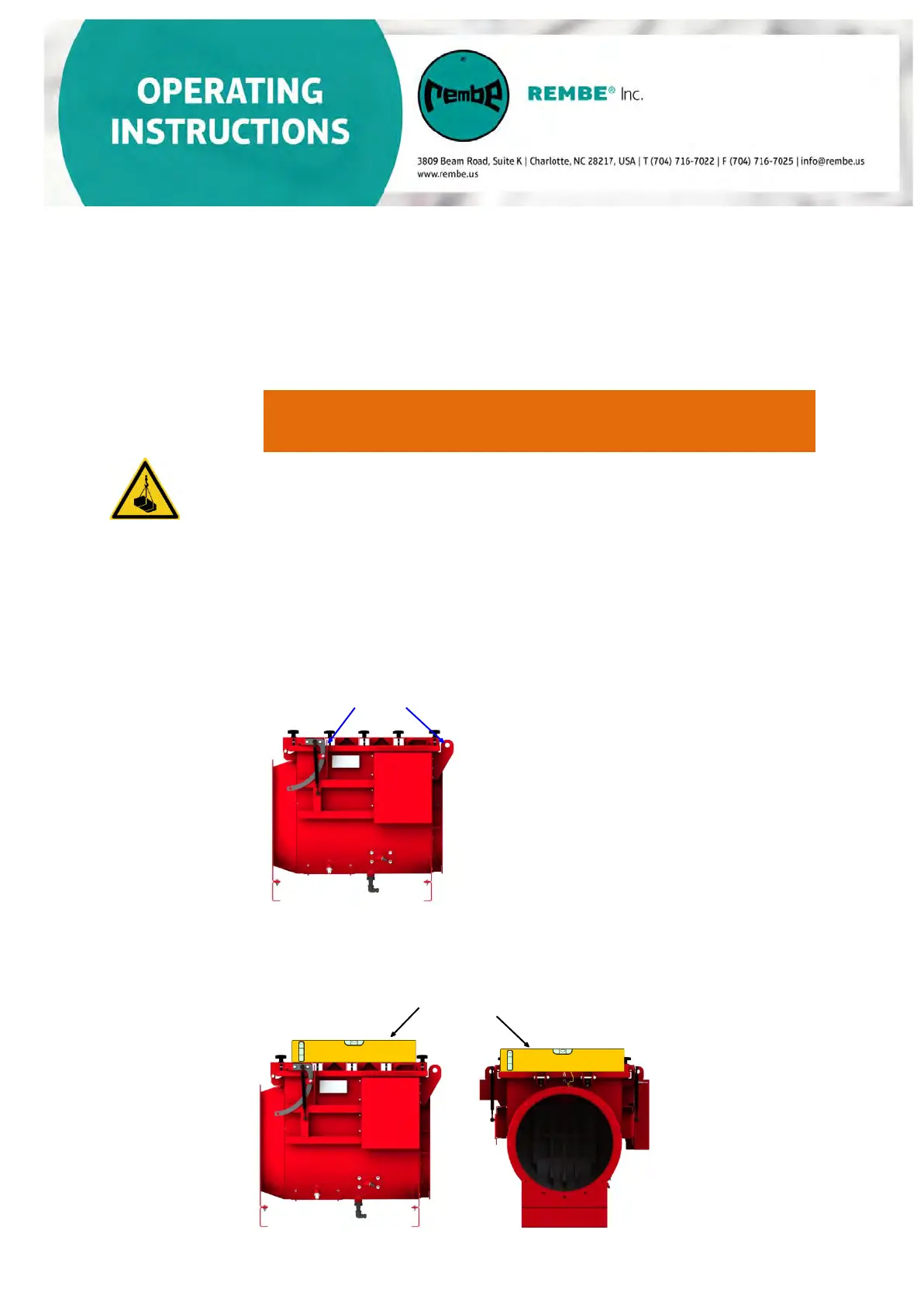
Lifting lugs
The entire inlet isolation device must be stabilized independently from the ductwork. Flanges
must be mounted tension-free to the connected ductwork.
When mounting the inlet isolation device, please be careful with the horizontal adjustment of the
inspection lid on both sides. Check it with a water level
.
Water level