page 59 of 91 USB-QFLCII-14804/0
g) Carefully close the flap blade after inspection/maintenance/service is complete.
Don't let the flap blade fall into the closed position—manually lower it slowly.
WARNING
Danger: there is a risk of harm to extremities from a falling/closing flap
blade!
Inspect
the flap blade prior to closing and control the lowering of the flap blade to
minimize the risk of harm.
--------------------------------------------------------------------------------------------------------
h) Re-attach the cover of the locking mechanism with the correct screws .
i) Close inspection lid (see Section 9.4, Inspection lid opening and closing )
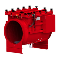
9.6 Check the bolted and
screwed connections
a) Ensure that the system is disconnected safely.
b) Check all bolted and screwed connections on the inlet isolation device.
9.7 Inspect the seals
a) Ensure that the system is disconnected safely.
b) Check the inlet isolation device for leakage.
c) Be sure to check the seal between the inlet isolation device and connected
duct-work as well as the inspection lid sealing.
d) Replace seals if damaged or leakage is detected
9.8 Check flap blade ease of movement
Please
proceed as follows:
a) Ensure that the system is disconnected safely.
b) Open the inspection lid as described in Section 9.4 Inspection lid opening and
closing
WARNING
Danger of head injuries due to protruding flap stopper when inspection
lid is opened!
Please watch out for the protruding flap blade stopper while working inside the inlet
isolation device. If necessary, equip the stopper with a bumper during the
maintenance
process. The bumper must be removed prior to closing the inspection lid.
--------------------------------------------------------------------------------------------------------
c) Remove the locking mechanism cover which is attached to the inlet isolation
device. All screws must be loosened and removed to remove the cover.