page 44 of 91 USB-QFLCII-14804/0
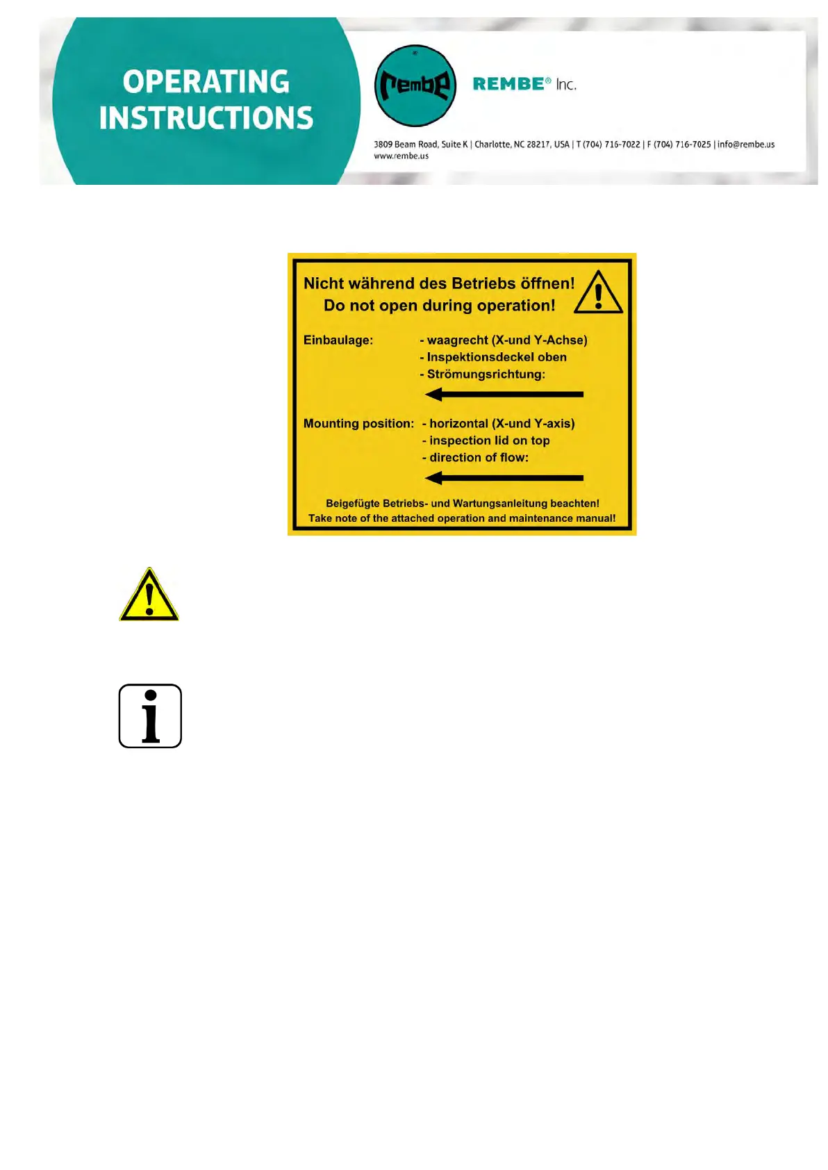
Please consider air flow direction when mounting!
The correct direction of flow is indicated in the safety instructions on the inlet isolation device!
The pressure surge resistance of the ductwork between the Q-FlapCompact II/Plus
and the protected container/filter unit must be at least the same as the pressure
surge resistance of the Q-FlapCompact II/Plus (generally minimum 2 mm sheet
thickness, welded piping system. For Pressure-shock resistance values of the
inlet isolation device, see section 1 Technical Data.
The minimum and maximum mounting distances between the inlet into the
protected container and the inlet isolation device connecting flange is
provided in section 6.3, Mounting distances and measures.
If the installation situation requires, the inlet isolation device can be
connected to the protected container by means of partially vertical-
running ductwork.
To improve the flow of the explosion shock wave into the inlet isolation device, the following
conditions must be fulfilled:
– The entire length (stretched length) of the ductwork between entry into
the protected container and connection flange of the inlet isolation device
must be longer than the minimum and maximum mounting distance.
– A straight pipe route must be available directly behind the inlet isolation
device.
– The required straight pipe route must measure at least five times the
nominal diameter of the ductwork.
Above the inlet isolation device, there should be enough space for
inspection and maintenance work between the flap and the ceiling (see
information regarding inspection lid range in Section 1, Technical Data.)