page 64 of 91 USB-QFLCII-14804/0
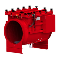
b) Loosen both locking unit mounting screws as shown below.
To adjust the
locking unit, the screws only have to be loosened but not removed.
Mounting screws
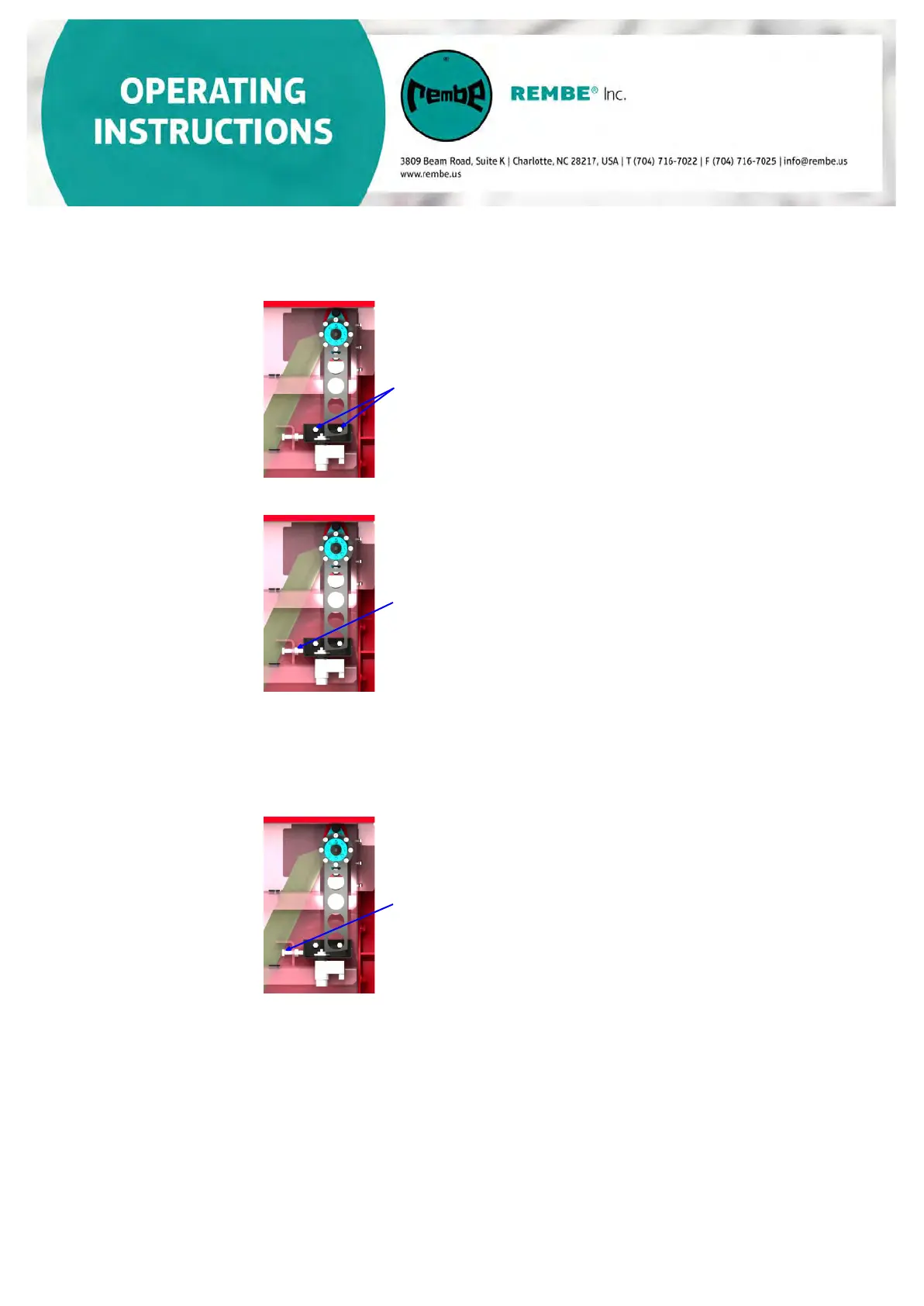
c) Loosen the counter nut of the latch pin.
Counter nut
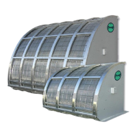
d)
Turn the setting screw at the stop and manually adjust the panel until the
required position is reached.
The locking unit is adjusted correctly if there is a gap of
approximately 1 mm (0.039 inches) between the locking unit and
the locking lever.
Adjusting bolt