R8C/20 Group, R8C/21 Group 12. Interrupts
Rev.2.00 Aug 27, 2008 Page 103 of 458
REJ09B0250-0200
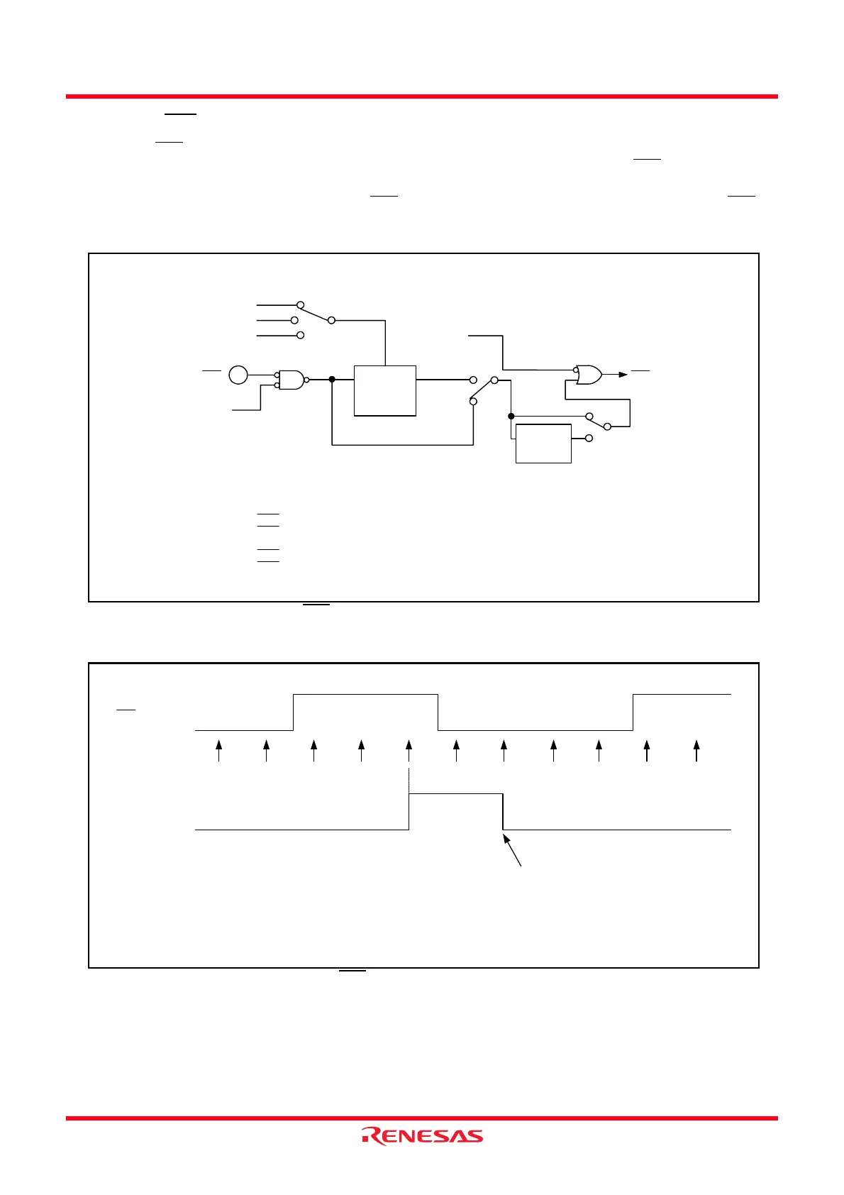
12.2.2 INTi Input Filter (i = 0 to 3)
The INTi input contains a digital filter. The sampling clock is selected by the INTiF1 to INTiF0 bits in the
INTF register. The IR bit in the INTiIC register is set to 1 (interrupt requested) when the INTi
level is sampled
for every sampling clock and the sampled input level matches three times.
Figure 12.14 shows the Configuration of INTi
Input Filter. Figure 12.15 shows Operating Example of INTi
Input Filter.
Figure 12.14 Configuration of INTi
Input Filter
Figure 12.15 Operating Example of INTi
Input Filter
i = 0 to 3
INTiF0, INTiF1: Bits in INTF register
INTiEN, INTiPL: Bits in INTEN register
= 01b
INTi
Port direction
register
(1)
Sampling clock
Digital filter
(input level
matches 3x)
INTi interrupt
= 10b
= 11b
f32
f8
f1
INTiF1 to INTiF0
INTiEN
Other than
INTiF1 to INTiF0
= 00b
=00b
INTiPL = 0
INTiPL = 1
NOTE:
1. INT0: Port P4_5 direction register
INT1: Port P1_5 direction register when using P1_5 pin
P1_7 direction register when using P1_7 pin
INT2: Port P6_6 direction register
INT3: Port P6_7 direction register
Both Edges
Detection
Circuit
INTi input
Sampling
timing
IR bit in
INTiIC register
Set to 0 in program
NOTE:
1. This is an operation example when the INTiF1 to INTiF0 bits in the
INTiF register is set to 01b, 10b, or 11b (passing digital filter).
i = 0 to 3
 Loading...