R8C/20 Group, R8C/21 Group 2. Central Processing Unit (CPU)
Rev.2.00 Aug 27, 2008 Page 10 of 458
REJ09B0250-0200
2. Central Processing Unit (CPU)
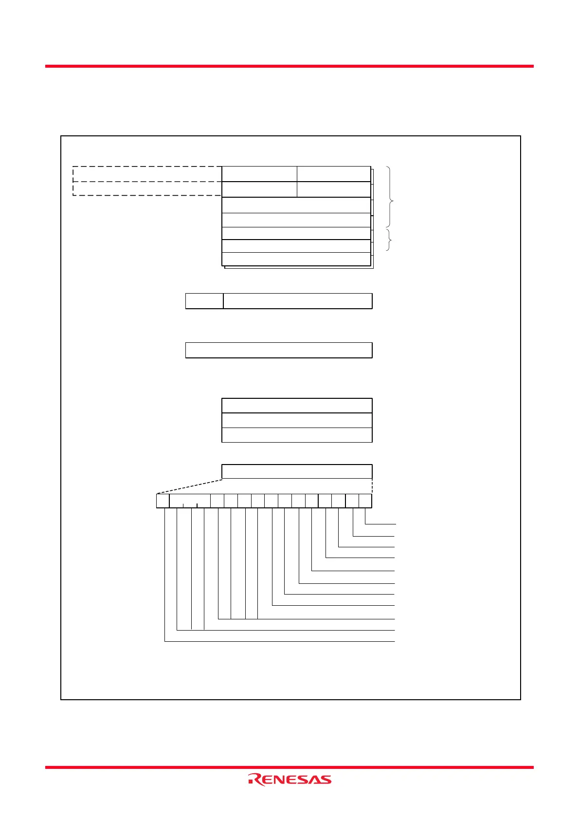
Figure 2.1 shows the CPU Registers. The CPU contains 13 registers. Of these, R0, R1, R2, R3, A0, A1, and FB
comprise a register bank. Two sets of register banks are provided.
Figure 2.1 CPU Registers
R2
b31
b15 b8b7
b0
Data registers
(1)
Address registers
(1)
R3
R0H (high-order of R0)
R2
R3
A0
A1
INTBH
b15b19
b0
INTBL
FB
Frame base registers
(1)
The 4-high order bits of INTB are INTBH and
the 16-low order bits of INTB are INTBL.
Interrupt table register
b19
b0
USP
Program counter
ISP
SB
User stack pointer
Interrupt stack pointer
Static base register
PC
FLG
Flag register
Carry flag
Debug flag
Zero flag
Sign flag
Register bank select flag
Overflow flag
Interrupt enable flag
Stack pointer select flag
Reserved area
Processor interrupt priority level
Reserved area
C
IPL
DZSBOIU
b15
b0
b15
b0
b15
b0
b8
b7
NOTE:
1. A register bank comprises these registers. Two sets of register banks are provided.
R0L (low-order of R0)
R1H (high-order of R1) R1L (low-order of R1)
 Loading...