R8C/20 Group, R8C/21 Group 17. Hardware LIN
Rev.2.00 Aug 27, 2008 Page 349 of 458
REJ09B0250-0200
17.4 Functional Description
17.4.1 Master Mode
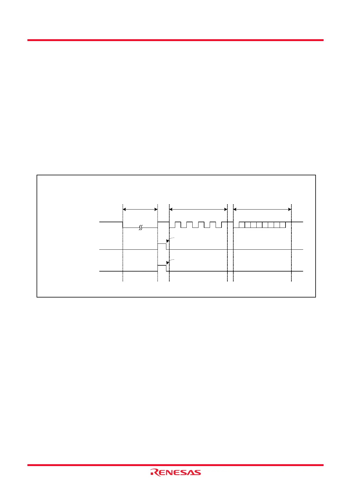
Figure 17.4 shows a Typical Operation when Sending a Header Field. Figure 17.5 and Figure 17.6 show an
Example of Header Field Transmission Flowchart.
When transmitting a header field, the hardware LIN operates as described below.
(1) When the TSTART bit in the TRACR register for timer RA is set by writing 1 in a program, the
hardware LIN outputs a low-level signal from the TXD0 pin for the period that is set in the TRAPRE
and TRA registers for timer RA.
(2) When timer RA underflows upon reaching the terminal count, the hardware LIN reverses the output of
the TXD0 pin and sets the SBDCT flag in the LINST register to 1. Furthermore, if the SBIE bit in the
LINCR register is set to 1, it generates a timer RA interrupt.
(3) The hardware LIN transmits 55h via UART0.
(4) The hardware LIN transmits an ID field via UART0 after it finished sending 55h.
(5) The hardware LIN performs communication for a response field after it finished sending the ID field.
Figure 17.4 Typical Operation when Sending a Header Field
TXD0 pin
Synch Break
1
0
SBDCT flag in the
LINST register
1
0
IR bit in the TRAIC
register
1
0
Synch Field IDENTIFIER
(1) (2) (3) (4) (5)
Set by writing 1 to the
B1CLR bit in the LINST
register
Cleared to 0 upon
acceptance of interrupt
request or by a program
• When LINE bit = 1 (Causes LIN to start operating), MST bit = 1 (Master mode), SBIE bit = 1
(Enables Synch Break detection interrupt)
 Loading...