R8C/20 Group, R8C/21 Group 17. Hardware LIN
Rev.2.00 Aug 27, 2008 Page 351 of 458
REJ09B0250-0200
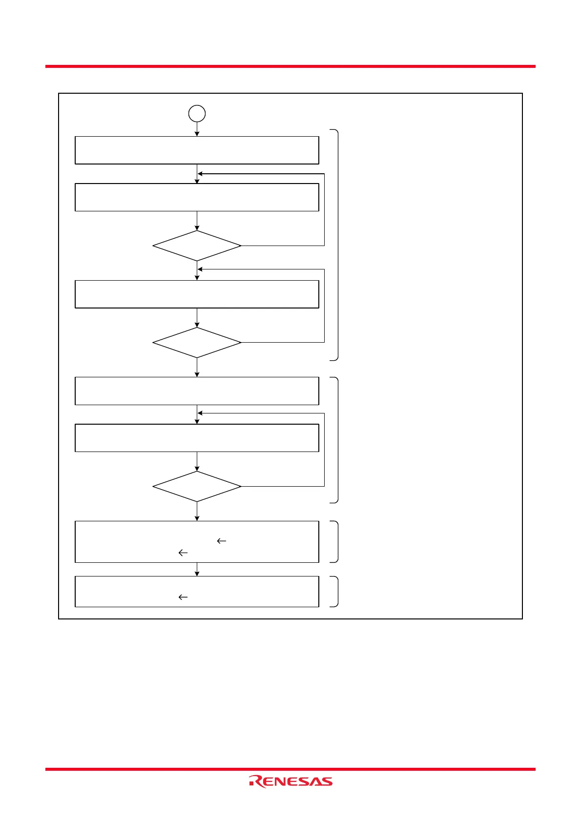
Figure 17.6 Example of Header Field Transmission Flowchart (2)
Timer RA Set the timer to start counting
TSTART bit in TRACR register
← 1
Timer RA Read the count status flag
TCSTF flag in TRACR register
Hardware LIN Read the Synch Break detection flag
SBDCT flag in LINST register
Timer RA Set the timer to stop counting
START bit in TRACR register
← 0
Timer RA Read the count status flag
TCSTF flag in TRACR register
UART0 Communication via UART0
TE bit in U0C1 register 1
U0TB register 0055h
The timer RA interrupt may be used
to terminate generation of Synch
Break.
Transmit the ID field.
A
TCSTF = 1?
SBDCT = 1?
YES
TCSTF = 0?
YES
UART0 Communication via UART0
U0TB register ID field
NO
YES
NO
NO
If the TRAPRE and TRA registers for
timer RA do not need to be read or
the register settings do not need to
be changed after writing 0 to the
TSTART bit, the procedure for
reading TCSTF flag = 0 can be
omitted.
Zero to one cycle of the timer RA
count source is required after timer
RA stops counting before the TCSTF
flag is set to 0.
Transmit the Synch Field.
After timer RA Synch Break is
generated, the timer should be made
to stop counting.
If the TRAPRE and TRA registers for
timer RA do not need to be read or
the register settings do not need to
be changed after writing 1 to the
TSTART bit, the procedure for
reading TCSTF flag = 1 can be
omitted.
Timer RA generates Synch Break.
Zero to one cycle of the timer RA
count source is required after timer
RA starts counting before the TCSTF
flag is set to 1.
One to two cycles of the CPU clock
are required after Synch Break
generation completes before the
SBDCT flag is set to 1.
 Loading...