R8C/20 Group, R8C/21 Group 7. Programmable I/O Ports
Rev.2.00 Aug 27, 2008 Page 38 of 458
REJ09B0250-0200
7. Programmable I/O Ports
There are 41 programmable Input/Output ports (I/O ports) P0 to P2, P3_0, P3_1, P3_3 to P3_5, P3_7, P4_3 to P4_5,
and P6. Also, P4_6 and P4_7 can be used as input-only ports if the XIN clock oscillation circuit is not used, and the
P4_2 can be used as an input-only port if the A/D converter is not used.
NOTES:
1. In input mode, whether the internal pull-up resistor is connected or not can be selected by the PUR0
and PUR1 registers.
2. When the A/D converter is not used, these ports can be used as the input port only.
3. When the XIN clock oscillation circuit is not used, these ports can be used as the input port only.
7.1 Functions of Programmable I/O Ports
The PDi_j (i = 0 to 4, 6, j = 0 to 7) bit in the PDi register controls I/O of the ports P0 to P2, P3_0, P3_1, P3_3 to
P3_5, P3_7, P4_3 to P4_5, and P6. The Pi register consists of a port latch to hold output data and a circuit to read
pin state.
Figures 7.1 to 7.7 show the Configurations of Programmable I/O Ports. Table 7.2 lists the Functions of
Programmable I/O Ports. Also, Figure 7.9 shows the PDi (i = 0 to 4 and 6) Registers. Figure 7.10 shows the Pi (i =
0 to 4 and 6) Registers, Figure 7.11 shows the Registers PUR0 and PUR1 and Figure 7.12 shows the PMR Register.
i = 0 to 4, 6, j = 0 to 7
NOTE:
1. Nothing is assigned to bits PD3_2, PD3_6, PD4_0 to PD4_2, PD4_6, and PD4_7.
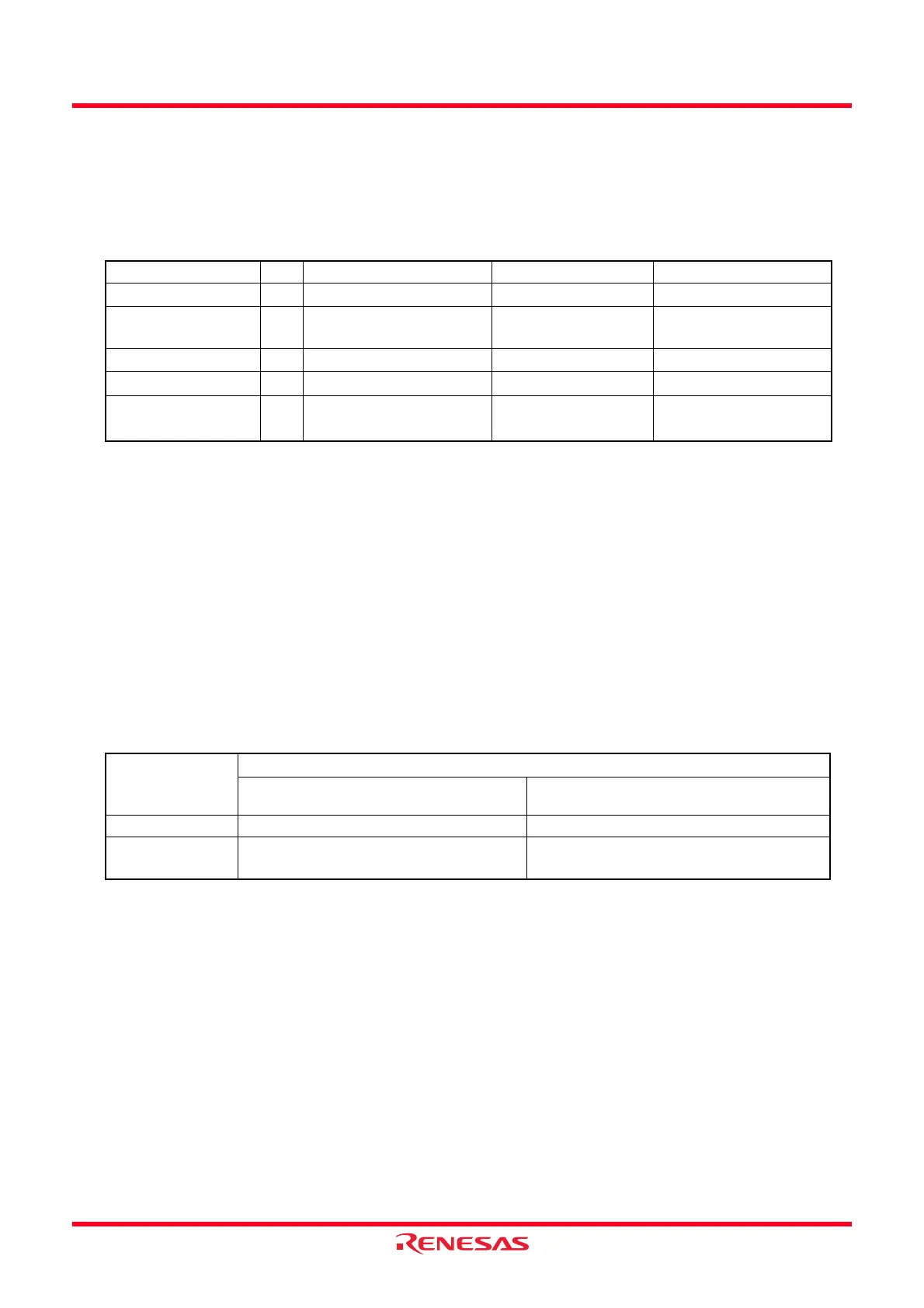
Table 7.1 Overview of Programmable I/O Ports
Ports I/O Type of Output I/O Setting Internal Pull-Up Resister
P0 to P2, P6 I/O CMOS3 state Set every bit
Set every 4 bits
(1)
P3_0, P3_1, P3_3 to
P3_5, P3_7
I/O CMOS3 state Set every bit
Set every 3 bits
(1)
P4_3 I/O CMOS3 state Set every bit
Set every bit
(1)
P4_4, P4_5 I/O CMOS3 state Set every bit
Set every 2 bits
(1)
P4_2
(2)
P4_6, P4_7
(3)
I (No output function) None None
Table 7.2 Functions of Programmable I/O Ports
Operation When
Accessing
Pi Register
Value of PDi_j Bit in PDi Register
(1)
When PDi_j bit is set to 0 (input mode) When PDi_j bit is set to 1 (output mode)
Reading Read pin input level Read the port latch
Writing Write to the port latch Write to the port latch. The value written in
the port latch, it is output from the pin.
 Loading...