R8C/20 Group, R8C/21 Group 6. Voltage Detection Circuit
Rev.2.00 Aug 27, 2008 Page 37 of 458
REJ09B0250-0200
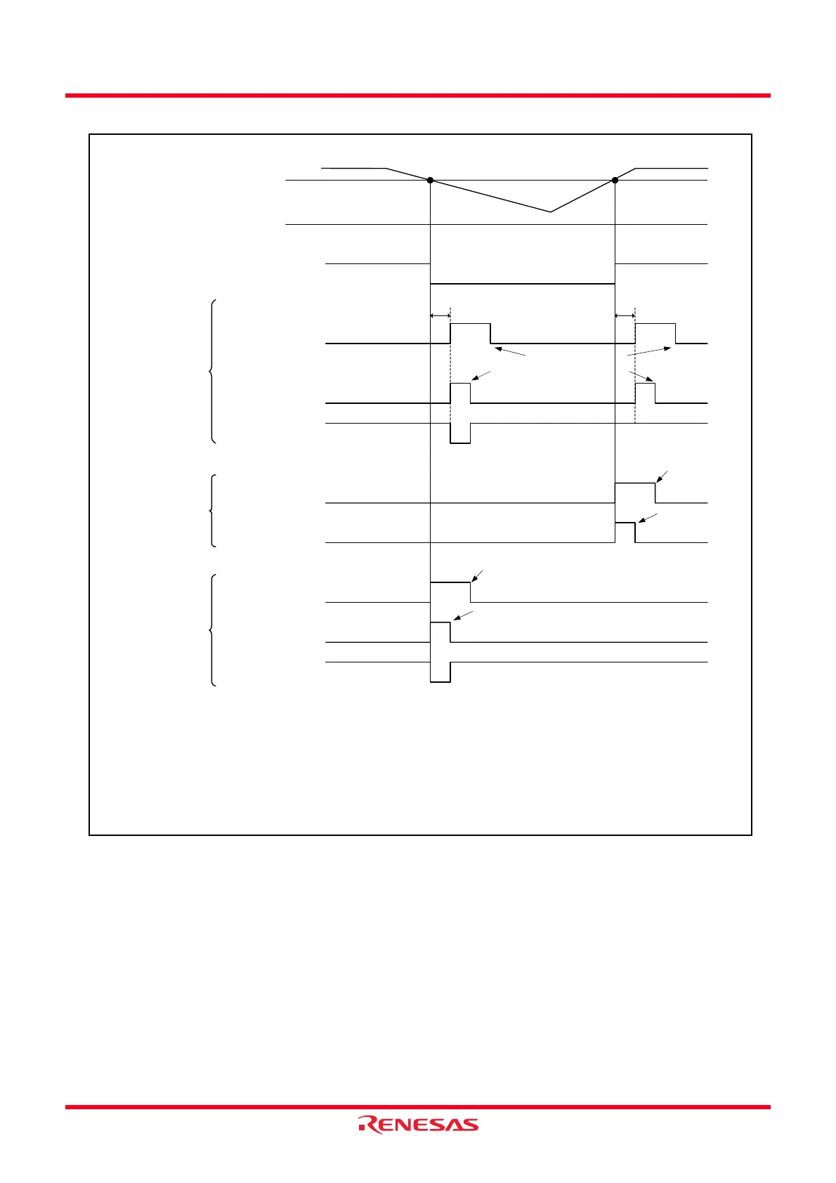
Figure 6.8 Example of Voltage Monitor 2 Interrupt and Voltage Monitor 2 Reset Operation
Vdet2
VCA13 bit
Internal reset signal
(VW2C6 = 1)
VCC
The above applies to the following conditions.
• VCA27 bit in VCA2 register = 1 (voltage detection 2 circuit enabled)
• VW2C0 bit in VW2C register = 1 (enables voltage monitor 2 interrupt and voltage monitor 2 reset)
NOTE:
1. When the voltage monitor 1 reset is not used, set the power supply to VCC
≥ 2.7.
2.7 V
(1)
0
1
Sampling clock of digital filter
x 4 cycles
VW2C2 bit
0
1
When the VW2C1 bit is set
to 0 (digital filter enabled)
VW2C2 bit
0
1
When the VW2C1 bit is
set to 1 (digital filter
disabled) and the
VW2C7 bit is set to 0
(Vdet2 or above)
VCA13 : Bit in VCA1 register
VW2C1, VW2C2, VW2C6, VW2C7 : Bit in VW2C register
Set to 0 by interrupt request
acknowledgement
Set to 0 by a program
Voltage monitor 2
interrupt request
(VW2C6 = 0)
Voltage monitor 2
interrupt request
(VW2C6 = 0)
VW2C2 bit
0
1
When the VW2C1 bit is
set to 1 (digital filter
disabled) and the
VW2C7 bit is set to 1
(Vdet2 or below)
Voltage monitor 2
interrupt request
(VW2C6 = 0)
Internal reset signal
(VW2C6 = 1)
Sampling clock of digital filter
x 4 cycles
Set to 0 by a program
Set to 0 by interrupt
request
acknowledgement
Set to 0 by a program
Set to 0 by interrupt
request acknowledgement
 Loading...