R8C/20 Group, R8C/21 Group 10. Clock Generation Circuit
Rev.2.00 Aug 27, 2008 Page 71 of 458
REJ09B0250-0200
The following describes the clocks generated by the clock generation circuit.
10.1 XIN Clock
This clock is supplied by a XIN clock oscillation circuit. This clock is used as the clock source for the CPU and
peripheral function clocks. The XIN clock oscillation circuit is configured by connecting a resonator between the
XIN and XOUT pins. The XIN clock oscillation circuit contains a feedback resistor, which is disconnected from
the oscillation circuit in stop mode in order to reduce the amount of power consumed in the chip. The XIN clock
oscillation circuit may also be configured by feeding an externally generated clock to the XIN pin.
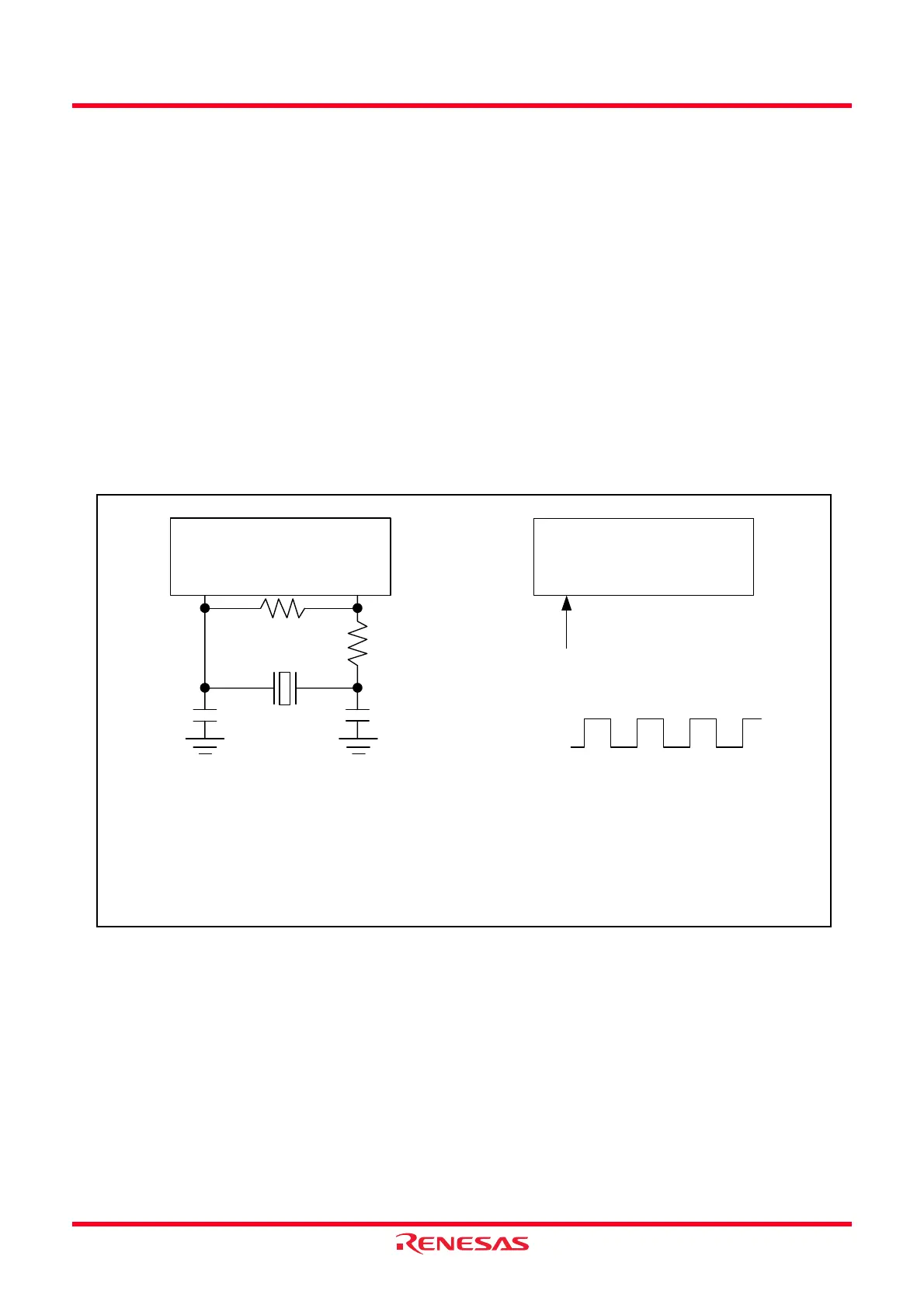
Figure 10.8 shows Examples of XIN Clock Connection Circuit. During or after reset, the XIN clock stops.
The XIN clock starts oscillating when the CM05 bit in the CM0 register is set to 0 (XIN clock on) after setting the
CM13 bit in the CM1 register to 1 (XIN- XOUT pin).
To use the XIN clock for the CPU clock source, set the OCD2 bit in the OCD register to 0 (select XIN clock) after
the XIN clock is oscillating stably.
The power consumption can be reduced by setting the CM05 bit in the CM0 register to 1 (stop XIN clock) if the
OCD2 bit is set to 1 (select on-chip oscillator clock).
When the clocks externally generated to the XIN pin are input, a XIN clock does not stop if setting the CM05 bit
to 1. If necessary, use an external circuit to stop the clock.
In stop mode, all clocks including the XIN clock stop. Refer to 10.4 Power Control for details.
Figure 10.8 Examples of XIN Clock Connection Circuit
XIN
XOUT
MCU
(built-in feedback resistor)
Rd
(1)
COUTCIN
XIN
XOUT
MCU
(built-in feedback resistor)
Externally derived clock
VCC
VSS
NOTE:
1. Insert a damping resistor if required. The resistance will vary depending on the oscillator and the oscillation drive
capacity setting. Use the value recommended by the maker of the oscillator.
Use high drive when oscillation starts and, if it is necessary to switch the oscillation drive capacity, do so after
oscillation stabilizes.
When the oscillation drive capacity is set to low, check that oscillation is stable. Also, if the oscillator manufacturer's
data sheet specifies that a feedback resistor be added external to the chip, insert a feedback resistor between XIN
and XOUT following the instruction.
Open
Ceramic resonator external circuit
External clock input clock
Rf
(1)
 Loading...