R8C/20 Group, R8C/21 Group 14. Timers
Rev.2.00 Aug 27, 2008 Page 258 of 458
REJ09B0250-0200
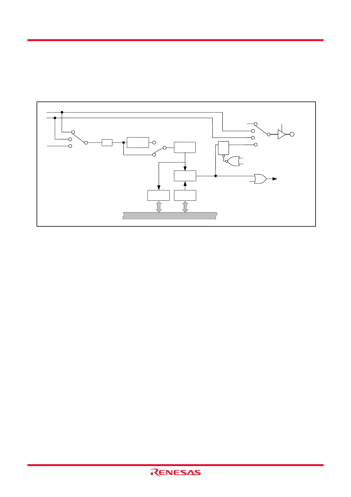
14.4.1 Output Compare Mode
The output compare mode is to count the internal count source divided-by-2 using the 4-bit or 8-bit counter and
detect the compare value match with the 8-bit counter.
Figure 14.114 shows the Block Diagram of Output Compare Mode and Table 14.37 lists the Output Compare
Mode Specifications. Figures 14.115 to 14.119 show the Registers Associated with Output Compare Mode and
Figure 14.120 shows the Operation in Output Compare Mode.
Figure 14.114 Block Diagram of Output Compare Mode
TOENA
TREO pin
f32
f4
f8
4-bit
counter
8-bit
counter
TRESEC
Comparison
circuit
TREMIN
1/2
RCS2 = 1
RCS2 = 0
COMIE
Timer RE interrupt
f2
Match
signal
= 00b
= 01b
= 10b
RCS1 to RCS0
RCS6 to RCS5
= 00b
= 01b
= 10b
= 11b
TOENA, TRERST: Bits in TRECR1 register
COMIE: Bit in TRECR2 register
RCS0 to RCS2, RCS5 to RCS6: Bits in TRECSR register
TQ
R
Reset
TRERST bit
Data bus
 Loading...