R8C/20 Group, R8C/21 Group 16. Clock Synchronous Serial Interface
Rev.2.00 Aug 27, 2008 Page 340 of 458
REJ09B0250-0200
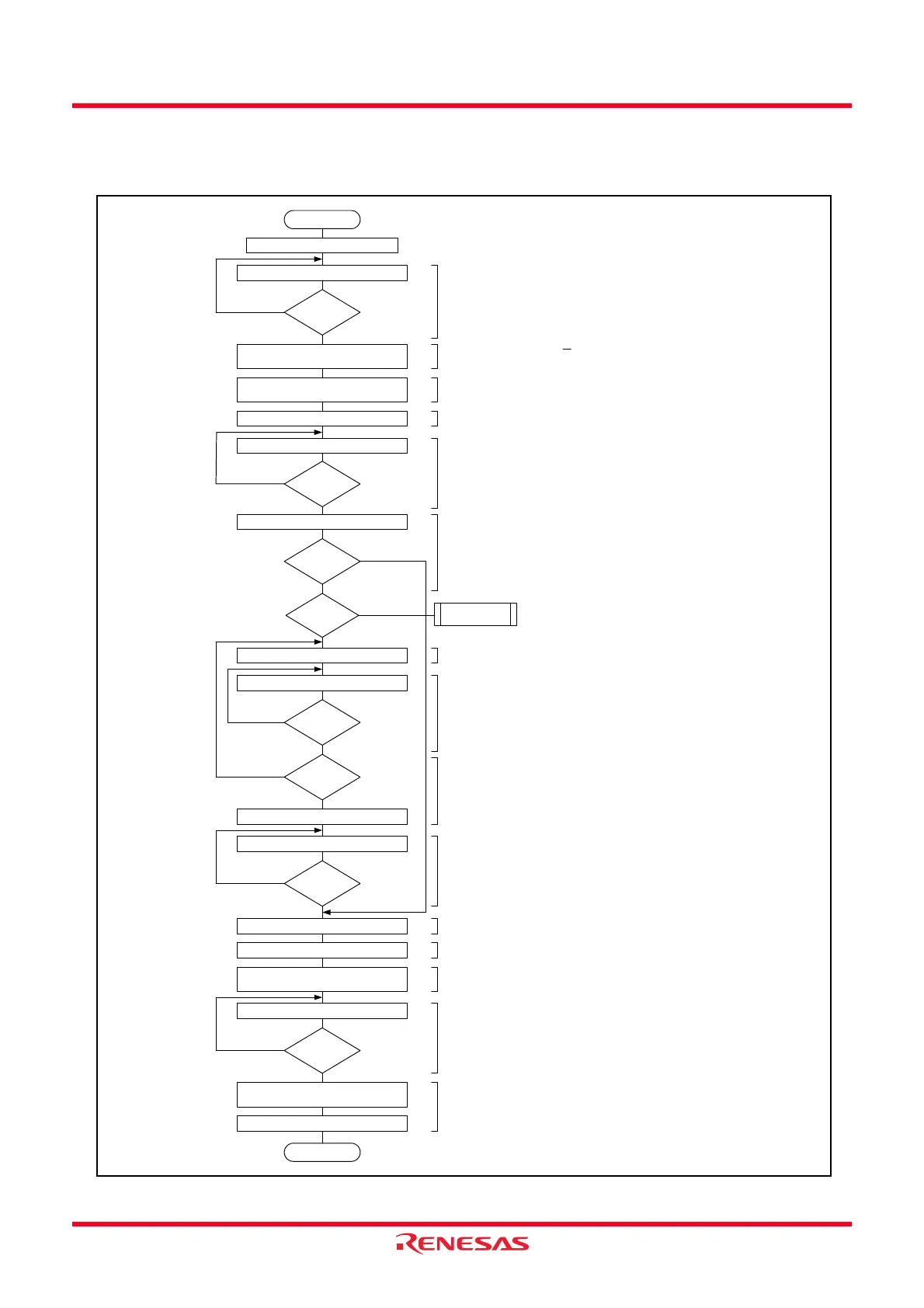
16.3.7 Examples of Register Setting
Figure 16.46 to Figure 16.49 show the Examples of Register Setting When Using I
2
C Bus Interface.
Figure 16.46 Example of Register Setting in Master Transmit Mode (I
2
C Bus Interface Mode)
Start
Initial setting
Read BBSY bit in ICCR2 register
End
BBSY = 0 ?
Write transmit data to ICDRT register
Transmit
mode ?
Master receive
mode
TEND = 1 ?
No
Yes
Yes
No
(1) Judge the state of the SCL and SDA lines
(2) Set to master transmit mode
(3) Generate the start condition
(4) Set the transmit data of the 1st byte
(slave address + R/W)
(5) Wait for 1 byte to be transmitted
(6) Judge the ACKBR bit from the specified slave device
(7) Set the transmit data after 2nd byte (except the last byte)
(8) Wait the ICDRT register is empty
(9) Set the transmit data of the last byte
(10) Wait for the transmit end of the last byte
(11) Set the TEND bit to 0
(12) Set the STOP bit to 0
(13) Generate the stop condition
(14) Wait the stop condition is generated
(15) Set to slave receive mode
Set the TDRE bit to 0
ICCR1 register TRS bit ← 1
MST bit ← 1
ICCR2 register SCP bit ← 0
BBSY bit ← 1
Read TEND bit in ICSR register
No
Read ACKBR bit in ICIER register
Yes
ACKBR = 0 ?
Write transmit data to ICDRT register
TDRE = 1 ?
Read TDRE bit in ICSR register
Last byte ?
Write transmit data to ICDRT register
TEND = 1 ?
Read TEND bit in ICSR register
ICSR register TEND bit ← 0
ICSR register STOP bit ← 0
ICCR2 register SCP bit ← 0
BBSY bit ← 0
Read STOP bit in ICSR register
STOP = 1 ?
ICCR1 register TRS bit ← 0
MST bit ← 0
ICSR register TDRE bit ← 0
No
Yes
No
Yes
No
Yes
No
Yes
No
Yes
(1)
(2)
(3)
(4)
(5)
(6)
(7)
(8)
(12)
(10)
(13)
(14)
(11)
(9)
(15)
- Set the STOP bit in the ICSR register to 0.
- Set the IICSEL bit in the PMR register to 1.
 Loading...