R8C/20 Group, R8C/21 Group 14. Timers
Rev.2.00 Aug 27, 2008 Page 213 of 458
REJ09B0250-0200
14.3.8 Reset Synchronous PWM Mode
Output 3 normal-phases and 3 counter-phases of the PWM waveform with the same period (no three-phase,
sawtooth wave modulation and dead time).
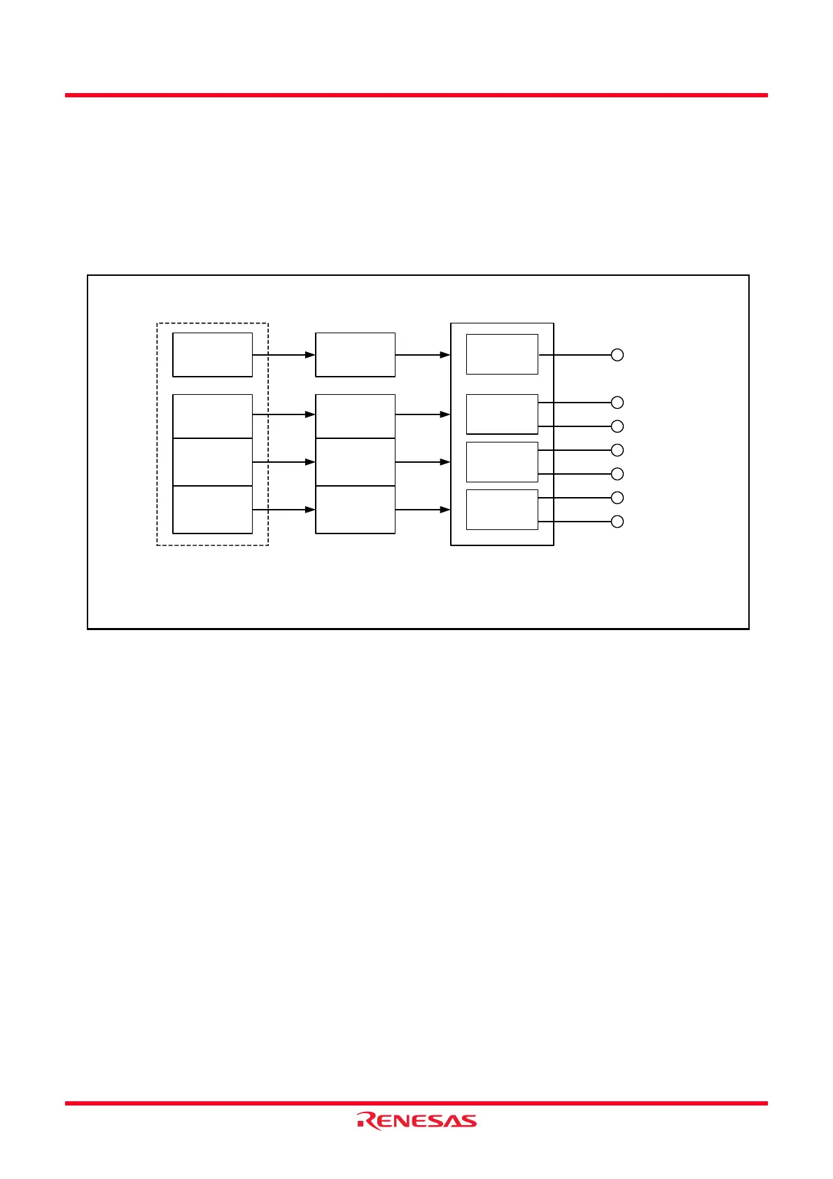
Figure 14.76 shows the Block Diagram of Reset Synchronous PWM Mode, Table 14.29 lists the Reset
Synchronous PWM Mode Specifications. Figures 14.77 to 14.84 show the Registers Associated with Reset
Synchronous PWM Mode and Figure 14.85 shows the Operating Example of Reset Synchronous PWM Mode.
Refer to Figure 14.75 Operating Example of PWM Mode (Duty 0%, Duty 100%) for the operation example
in PWM Mode of duty 0% and duty 100%.
Figure 14.76 Block Diagram of Reset Synchronous PWM Mode
Period
TRDIOC0
TRDIOB0
TRDIOD0
TRDIOA1
TRDIOC1
TRDIOB1
TRDIOD1
PWM1
PWM2
PWM3
Waveform control
TRDGRB0
register
TRDGRA1
register
TRDGRB1
register
Normal-phase
Counter-phase
TRDGRA0
register
TRDGRD0
register
TRDGRC1
register
TRDGRD1
register
TRDGRC0
register
Buffer
(1)
Normal-phase
Counter-phase
Normal-phase
Counter-phase
NOTE:
1. When the BFC0, BFD0, BFC1 and BFD1 bits in the TRDMR register are set to 1 (buffer register).
 Loading...