R8C/20 Group, R8C/21 Group 14. Timers
Rev.2.00 Aug 27, 2008 Page 222 of 458
REJ09B0250-0200
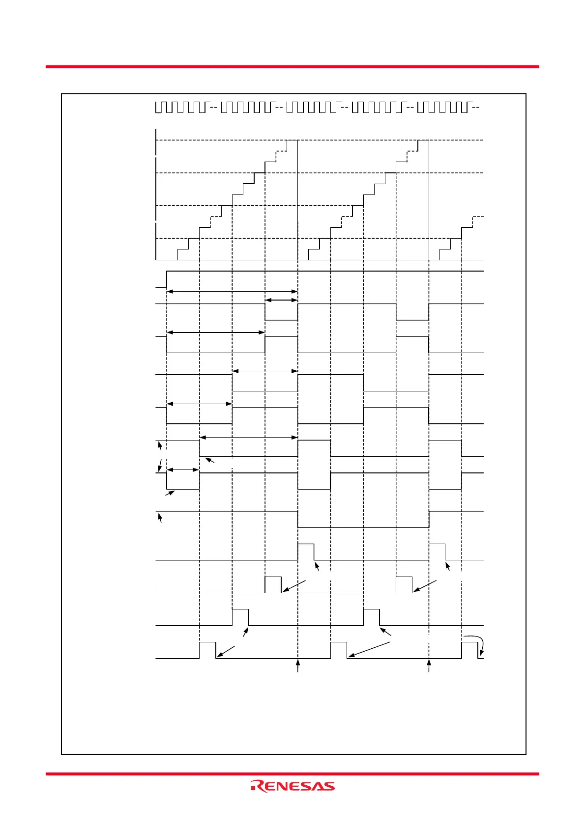
Figure 14.85 Operating Example of Reset Synchronous PWM Mode
Initial output “H”
Active level “L”
m
n
p
Value in TRD0 register
Count source
m + 1
TRDIOD0 output
q
m - n
TRDIOD1 output
m: Setting value in TRDGRA0 register
n: Setting value in TRDGRB0 register
p: Setting value in TRDGRA1 register
q: Setting value in TRDGRB1 register
Active level “L”
Set to 0 by a program
TRDIOB0 output
IMFA bit in
TRDSR0 register
1
0
IMFB bit in
TRDSR0 register
1
0
IMFA bit in
TRDSR1 register
1
0
IMFB bit in
TRDSR1 register
1
0
TSTARTi bit in
TRDSTR register
1
0
n + 1
TRDIOC1 output
TRDIOA1 output
m - q
m - p
TRDIOB1 output
TRDIOC0 output
p + 1
Initial output “H”
i = 0 or 1
The above applies to the following conditions:
The OLS1 and OLS0 bits in the TRDFCR register are set to 0. (initial output level “H”, active level “L”)
0000h
Set to 0 by a program
Set to 0 by a program
Set to 0 by a program
Transfer from the buffer register to the
general register at the buffer operation
Transfer from the buffer register to the
general register at the buffer operation
q + 1
 Loading...