R8C/20 Group, R8C/21 Group 14. Timers
Rev.2.00 Aug 27, 2008 Page 146 of 458
REJ09B0250-0200
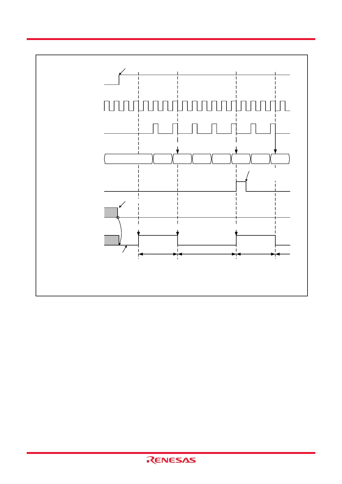
Figure 14.20 Operation Example of Timer RB in Programmable Waveform Generation Mode
1
0
1
0
IR bit in TRBIC
register
1
0
Count source
Timer RB prescaler
underflow signal
Counter of timer RB
TRBO pin output
TOPL bit in TRBIO
register
Set to 1 by program
Set to 0 when interrupt
request is acknowledged,
or set by program
The above applies to the following conditions.
TSTART bit in TRBCR
register
1
0
01h 00h 02h
Timer RB secondary reloads Timer RB primary reloads
Set to 0 by program
TRBPRE = 01h, TRBPR = 01h, TRBSC = 02h
TRBIOC register TOCNT = 0 (timer RB waveform is output from the TRBO pin)
02h 01h 00h 01h 00h
Primary period Primary periodSecondary period
Waveform output starts Waveform output inverts Waveform output starts
Initial output is the same level
as during secondary period.
 Loading...