R8C/20 Group, R8C/21 Group 14. Timers
Rev.2.00 Aug 27, 2008 Page 181 of 458
REJ09B0250-0200
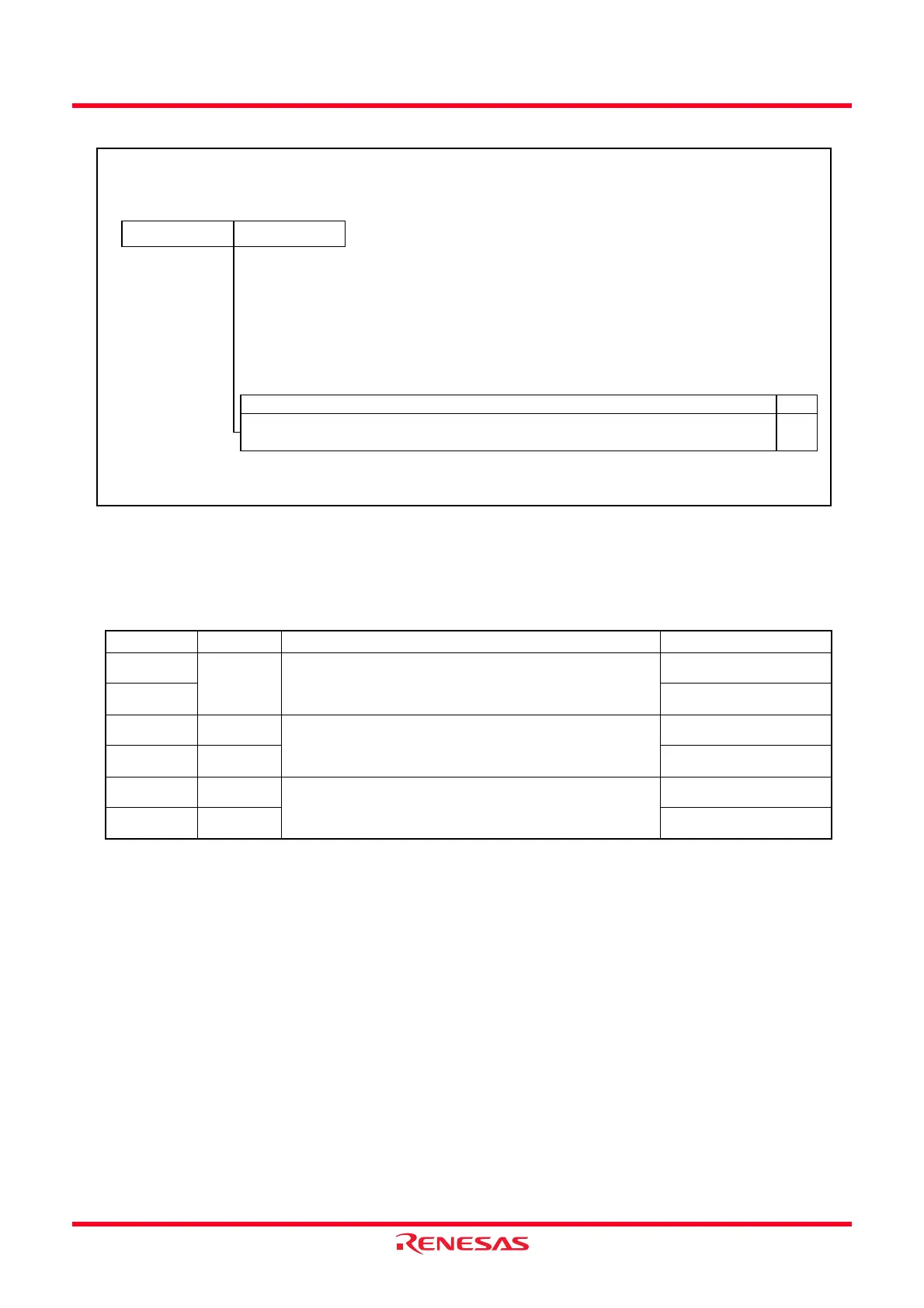
Figure 14.44 Registers TRDGRAi, TRDGRBi, TRDGRCi and TRDGRDi in Input Capture Function
The following registers are disabled in the input capture function:
TRDOER1, TRDOER2, TRDOCR, TRDPOCR0 and TRDPOCR1
i = 0 or 1, j = either A, B, C or D
BFCi, BFDi: Bits in TRDMR Register
Set the pulse width of the input capture signal applied to the TRDIOji pin to 3 cycles or more of the Timer RD
operation clock (refer to Table 14.11 Timer RD Operation Clocks) for “no digital filter” (the DFj bit in the
TRDDFi register is set to 0).
Table 14.24 TRDGRji Register Functions in Input Capture Function
Register Setting Register Function Input-Capture Input Pin
TRDGRAi − General register
The value in the TRDi register can be read at the input
capture.
TRDIOAi
TRDGRBi TRDIOBi
TRDGRCi BFCi = 0 General register
The value in the TRDi register can be read at the input
capture.
TRDIOCi
TRDGRDi BFDi = 0 TRDIODi
TRDGRCi BFCi = 1 Buffer register
The value in the TRDi register can be read at the input
capture. (Refer to 14.3.2 Buffer Operation)
TRDIOAi
TRDGRDi BFDi = 1 TRDIOBi
Timer RD General Register Ai, Bi, Ci and Di (i = 0 or 1)
(1)
Symbol Address After Reset
TRDGRA0
TRDGRB0
TRDGRC0
TRDGRD0
TRDGRA1
TRDGRB1
TRDGRC1
TRDGRD1
0149h-0148h
014Bh-014Ah
014Dh-014Ch
014Fh-014Eh
0159h-0158h
015Bh-015Ah
015Dh-015Ch
015Fh-015Eh
FFFFh
FFFFh
FFFFh
FFFFh
FFFFh
FFFFh
FFFFh
FFFFh
RW
NOTE:
1.
(b8)
b0
(b15)
b7
b0b7
RW
Function
Refer to
Table 14.24 TRDGRji Register Functions in Input Capture Function
Access the TRDGRAi to TRDGRDi registers in 16-bit units. Do not access them in 8-bit units.
 Loading...