R8C/20 Group, R8C/21 Group 14. Timers
Rev.2.00 Aug 27, 2008 Page 183 of 458
REJ09B0250-0200
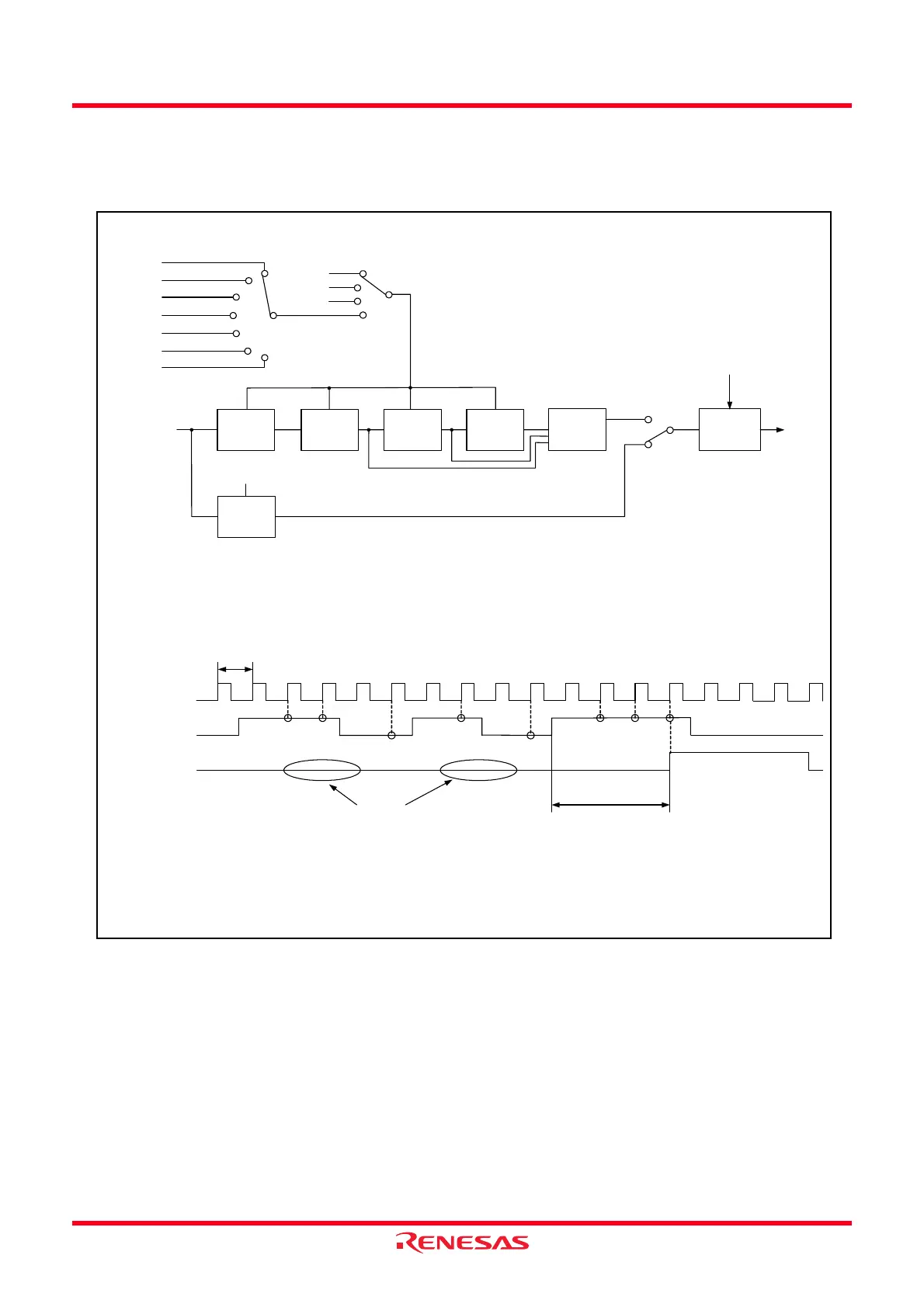
14.3.5.1 Digital Filter
The TRDIOji input is sampled, and when the sampled input level matches 3 times, its level is assumed as a
determination. Select the digital filter function and sampling clock by the TRDDFi register.
Figure 14.46 Block Diagram of Digital Filter
C
DQ
Latch
C
DQ
Latch
C
DQ
Latch
Match
detection
circuit
Edge detection
circuit
DFj
Sampling clock
IOA2 to IOA0
IOB2 to IOB0
IOC3 to IOC0
IOD3 to IOD0
DFCK1 to DFCK0
TRDIOji input signal
Clock period selected by the
TCK2 to TCK0 bits
or DFCK1 to DFCK0 bits
Sampling clock
TRDIOji input signal
Input signal through
digital filtering
Transmission cannot be
performed without 3-times match
because the input signal is
assumed as noise.
Signal transmission delayed
up to 5-sampling clock
Recognition of the
signal change with
3-time match
f32
f8
f1
i = 0 or 1, j = either A, B, C or D
TCK0 to TCK2: Bits in TRDCRi register
DFCK0 to DFCK1 and DFj: Bits in TRDDF register
IOA0 to IOA2 and IOB0 to IOB2: Bits in TRDIORAi register
IOC0 to IOC3 and IOD0 to IOD3: Bits in TRDIORCi register
C
DQ
Latch
C
DQ
Latch
Timer RD operation clock
f1, fOCO40M
Count source
=101b
=100b
=011b
=110b
=010b
=001b
fOCO40M
f4
f2
f8
f32
TRDCLK
f1
=000b
=00b
=01b
=10b
=11b
TCK2 to TCK0
1
0
 Loading...