R8C/20 Group, R8C/21 Group 14. Timers
Rev.2.00 Aug 27, 2008 Page 190 of 458
REJ09B0250-0200
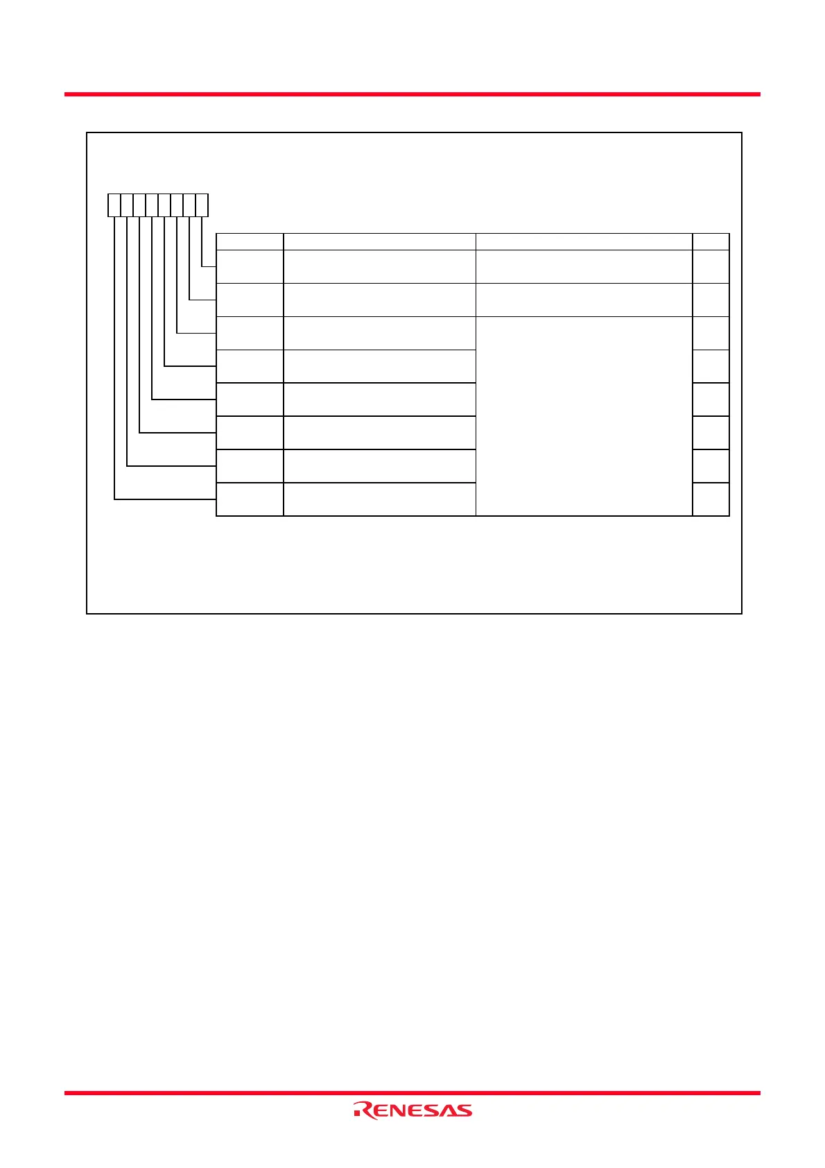
Figure 14.52 TRDOCR Register in Output Compare Function
Timer RD Output Control Register
(1,2)
Symbol Address After Reset
TRDOCR
013Dh 00h
Bit Symbol Bit Name Function RW
NOTES:
1.
2.
TOA1
TOB1 RW
TRDIOD1 initial output level selection
bit
0 : “L”
1 : “H”
TRDIOB1 initial output level selection
bit
TOC1
TRDIOC1 initial output level selection
bit
TRDIOC0 initial output level selection
bit
Write to the TRDOCR register w hen both the TSTART0 and TSTART1 bits in the TRDSTR register are set to 0 (count
stops).
TOC0 RW
RW
TRDIOA1 initial output level selection
bit
RW
RW
TRDIOD0 initial output level selection
bit
TOD1 RW
RW
TOB0 RW
TRDIOA0 output level selection bit 0 : Initial output “L”
1 : Initial output “H”
TRDIOB0 output level selection bit 0 : Initial output “L”
1 : Initial output “H”
TOA0
b7 b6 b5 b4
When the pin functions are w aveform output (refer to
Table 14.12
to
14.19
) and the TRDOCR register is set, the
initial output level is output.
b3 b2
TOD0
b1 b0
 Loading...