R8C/20 Group, R8C/21 Group 20. Electrical Characteristics
Rev.2.00 Aug 27, 2008 Page 424 of 458
REJ09B0250-0200
NOTE:
1. V
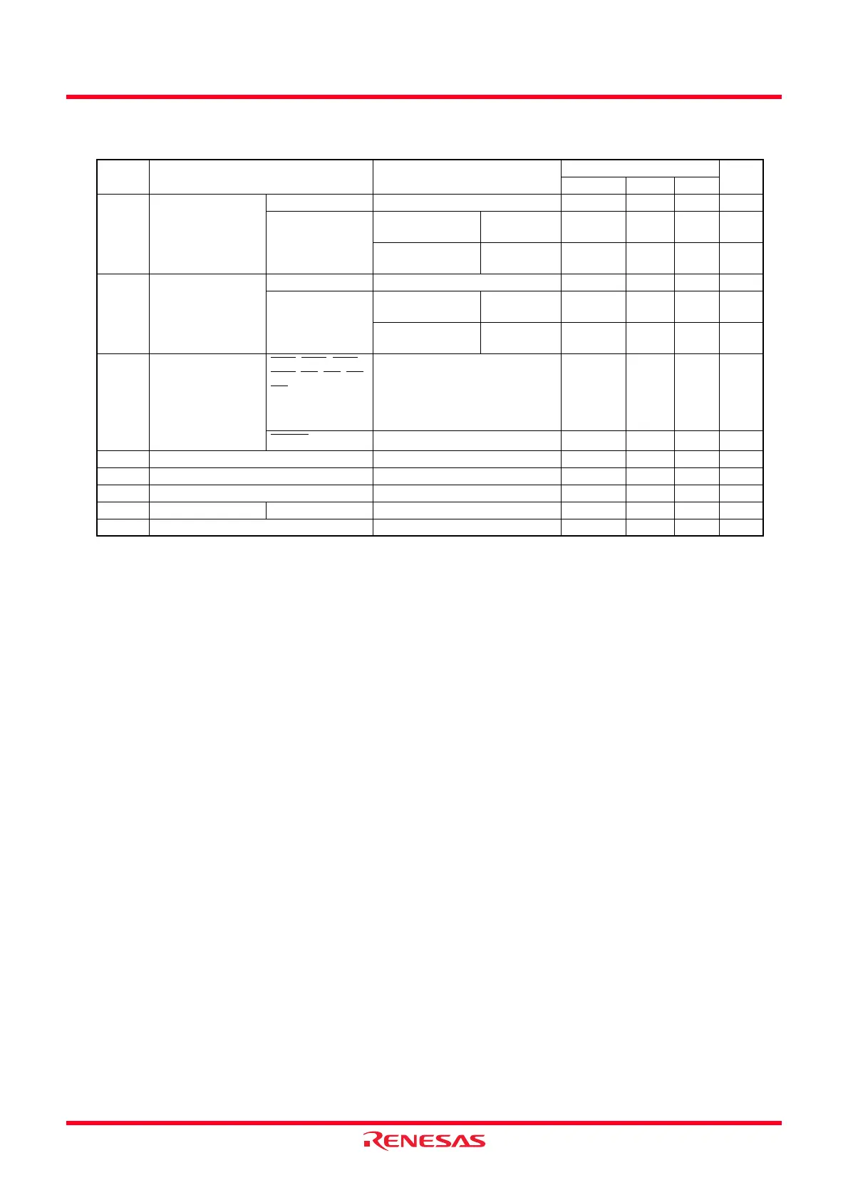
CC = 2.7 to 3.3 V at Topr = -40 to 85°C (J version) / -40 to 125°C (K version), f(XIN) = 10 MHz, unless otherwise specified.
Table 20.20 Electrical Characteristics (3) [VCC = 3 V]
Symbol Parameter Condition
Standard
Unit
Min. Typ. Max.
V
OH Output “H” voltage Except XOUT IOH = -1 mA VCC − 0.5 − VCC V
XOUT Drive capacity
HIGH
I
OH = -0.1 mA VCC − 0.5 − VCC V
Drive capacity
LOW
I
OH = -50 µAVCC − 0.5 − VCC V
V
OL Output “L” voltage Except XOUT IOL = 1 mA −−0.5 V
XOUT Drive capacity
HIGH
I
OL = 0.1 mA −−0.5 V
Drive capacity
LOW
I
OL = 50 µA −−0.5 V
V
T+-VT- Hysteresis
INT0
, INT1, INT2,
INT3
, KI0, KI1, KI2,
KI3
, TRAIO, RXD0,
RXD1, CLK0, SSI,
SCL, SDA, SSO
0.1 0.3
− V
RESET
0.1 0.4 − V
I
IH Input “H” current VI = 3 V, VCC = 3 V −−4.0 µA
I
IL Input “L” current VI = 0 V, VCC = 3 V −−-4.0 µA
R
PULLUP Pull-up resistance VI = 0 V, VCC = 3 V 66 160 500 kΩ
RfXIN Feedback resistance XIN − 3.0 − MΩ
VRAM RAM hold voltage During stop mode 2.0 −−V
 Loading...