R8C/1A Group, R8C/1B Group 17. A/D Converter
Rev.1.30 Dec 08, 2006 Page 234 of 315
REJ09B0252-0130
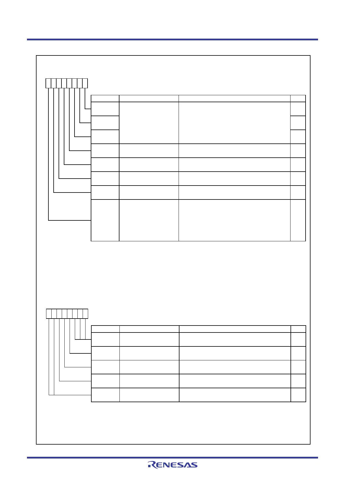
Figure 17.2 Registers ADCON0 and ADCON1
A/D Control Register 0
(1)
Symbol Address After Reset
ADCON0 00D6h 00000XXXb
Bit Symbol Bit Name Function RW
NOTE :
1.
2.
3.
4.
After changing the A/D operating mode, select the analog input pin again.
Set øAD frequency to 10 MHz or below .
CKS0
Frequency select bit 0 [When CKS1 in ADCON1 register = 0]
0 : Selects f4.
1 : Selects f2.
[When CKS1 in ADCON1 register = 1]
0 : Selects f1.
(4)
1 : fRING-fast
RW
If the ADCON0 register is rew ritten during A/D conversion, the conversion result is undefined.
Bits CH0 to CH2 are enabled w hen the ADGSEL0 bit is set to 1.
ADST
A/D conversion start flag 0 : Disabes A/D conversion.
1 : Starts A/D conversion.
RW
ADCAP
A/D conversion automatic
start bit
0 : Starts at softw are trigger (ADST bit).
1 : Starts at capture (timer Z interrupt request).
RW
0 : One-shot mode
1 : Repeat mode
RW
RW
ADGSEL0 RW
A/D input group select bit 0 : Disabled
1 : Enabled (AN8 to AN11)
CH1 RW
CH0
CH2 RW
Analog input pin select
bits
(2)
b2 b1 b0
1 0 0 : AN8
1 0 1 : AN9
1 1 0 : AN10
1 1 1 : AN11
Other than above: Do not set.
MD
A/D operating mode select
bit
(3)
b7 b6 b5 b4
1
b3 b2 b1 b0
1
A/D Control Register 1
(1)
Symbol Address After Reset
ADCON1
00D7h 00h
Bit Symbol Bit Name Function RW
NOTES :
1.
2.
3. When the VCUT bit is set to 1 (connected) from 0 (not connected), w ait for 1 µs or more before starting
A/D conversion.
b3 b2
VCUT
b1 b0
00
Refer to the description of the CKS0 bit in the
ADCON0 register function.
b7 b6 b5 b4
—
(b2-b0)
00 0
RW
If the ADCON1 register is rew ritten during A/D conversion, the conversion result is undefined.
CKS1 RW
RW
RW
—
(b6-b7)
Reserved bits
Vref connect bit
(3)
0 : Vref not connected
1 : Vref connected
Set the BITS bit to 0 (8-bit mode) in repeat mode.
Reserved bits Set to 0.
8/10-bit mode select bit
(2)
0 : 8-bit mode
1 : 10-bit mode
RW
Set to 0.
Frequency select bit 1
BITS
 Loading...


