R8C/1A Group, R8C/1B Group 19. Electrical Characteristics
Rev.1.30 Dec 08, 2006 Page 282 of 315
REJ09B0252-0130
NOTES:
1. The measurement condition is V
CC = 5.0 V and Topr = 25 °C.
2. Refer to
10.6.5 High-Speed On-Chip Oscillator Clock for notes on high-speed on-chip oscillator clock.
3. The standard value shows when the HRA1 register is assumed as the value in shipping and the HRA2 register value is set to
00h.
NOTES:
1. The measurement condition is V
CC = 2.7 to 5.5 V and Topr = 25 °C.
2. Waiting time until the internal power supply generation circuit stabilizes during power-on.
3. Time until CPU clock supply starts after the interrupt is acknowledged to exit stop mode.
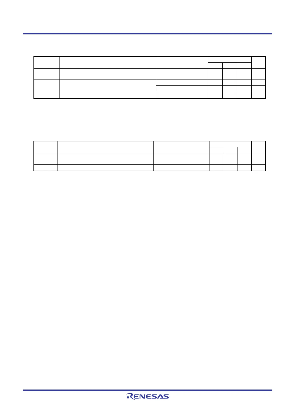
Table 19.10 High-Speed On-Chip Oscillator Circuit Electrical Characteristics
Symbol Parameter Condition
Standard
Unit
Min. Typ. Max.
− High-speed on-chip oscillator frequency when the
reset is deasserted
VCC = 5.0 V, Topr = 25 °C − 8 − MHz
− High-speed on-chip oscillator frequency
temperature
• supply voltage dependence
(2)
0 to +60 °C/5 V ± 5 %
(3)
7.76 − 8.24 MHz
-20 to +85 °C/2.7 to 5.5 V
(3)
7.68 − 8.32 MHz
-40 to +85 °C/2.7 to 5.5 V
(3)
7.44 − 8.32 MHz
Table 19.11 Power Supply Circuit Timing Characteristics
Symbol Parameter Condition
Standard
Unit
Min. Typ. Max.
t
d(P-R) Time for internal power supply stabilization during
power-on
(2)
1 − 2000 µs
t
d(R-S)
STOP exit time
(3)
−−150 µs
 Loading...


