18
Assemblyoftherightsidepart(frontview)
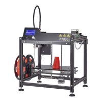
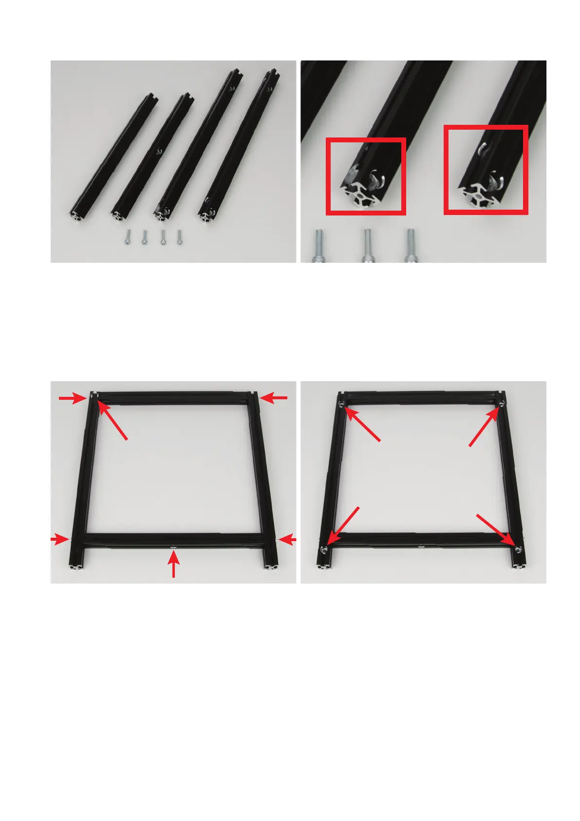
1xaluminiumprole284mmwithoutbore
1xaluminiumprole284mmwithboreatthecentre
1xaluminiumprole356mmwith4boresand1cut-outfortheballbearing
1xaluminiumprole356mmwith4bores
4x cylinder head screw M5x20
Thetwoshortprolesarethesameonbothsides.
Inthelongprolewiththecut-outfortheballbearing,thecutsideof
the bore, at the height of the cut-out for the ball bearing, must be on
theright(leftredbox).
Inthesecondlongprole,themilledpartoftheupperbore,totheright
of the milled side of the bore, must be below.
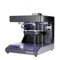
Assemblethe4aluminiumprolesasillustrated.Screwonecylinder
headscrewintoeachofthe4bores(2),butdonottightenthescrews
yet. All parts must remain movable.
Thisgureshowstherightsidepartfromtheinside.Thecut-outfor
theballbearingmustbeattheupperleft(1).
Themilledsidesoftheboremustpointtotheoutsideeach(2).The
screws also need to be inserted into the respective bore from the
milledsidebore(2).
Themilledsideoftheboreinthelowercross-prolemustpointdown
(3).
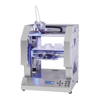
Thisgureshowstherightsidepartfromtheoutside.
Asthegureshows,themilledsidesofthe4boresoftheouterpro-
lesmustpointup(seethe4arrows).
1
22
22
3