54
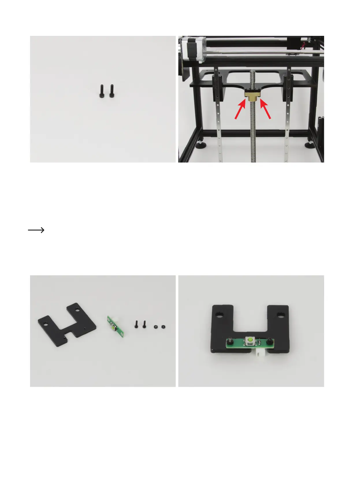
Attachtheangenuttothetable.
2x cylinder head screw M4x16 black Liftthetableandturntheangenutalmostallthewayup.Putthe
table back down on it.
Turn the two cylinder-head screws into the thread bores of the table
throughtheboresoftheangenutfrombelow.
Tighten the screws.
Optionally, the screws can be secured with threadlocker varnish.
Lower the table again by turning the spindle.
Ifyoundwhenturningthetableupordownsubsequentlythatitmovesstifyatthetoporbottom,releasetheattachmentscrews
ofthetwoguiderailsinsequence.Tightenthescrewagainbeforereleasingthenextone.Youmayneedtoreleasetheundertable
or the tappets again as well.
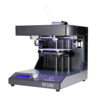
AssemblyoftheZ-limitswitch
1x limit switch holder plate
1x limit switch PCB
2x cylinder head screw M2x8 black
2x nut M2 black
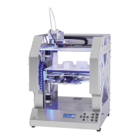
Mount the limit switch PCB on the limit switch holder plate as illus-
trated with the two M2-cylinder-head screws and M2 nuts. The cut-out
and the limit switch must be aligned as illustrated. The two nuts must
be installed on the side of the limit switch.