67
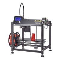
PushingontheadapterPCB
1x additional PCB
1x adapter PCB
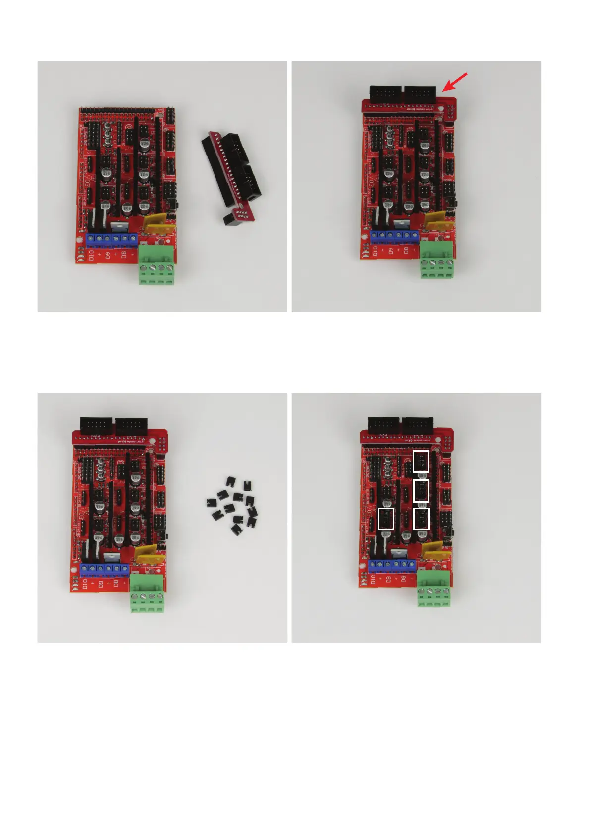
Push the adapter PCB onto the additional PCB as illustrated. All pins
in the adapter PCB must be pushed into the socket strip.
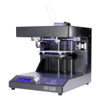
PushingthejumpersontotheadditionalPCB
1x additional PCB
12x jumper
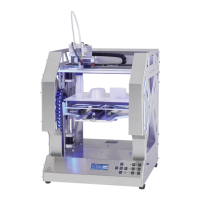
6 pins each are placed between the continuous pin series into which
themotordriversareinsertedlater(2rowswith3pinseach).3jump-
erseachmustbeputontothesepins.Thereare3eldsontheright
sideofthePCB(motorsX,YandZ),andoneeldontheleftside
(lamentinfeed).
Puton3jumperspereldasillustrated.
The5theldattheupperleftremainsempty.