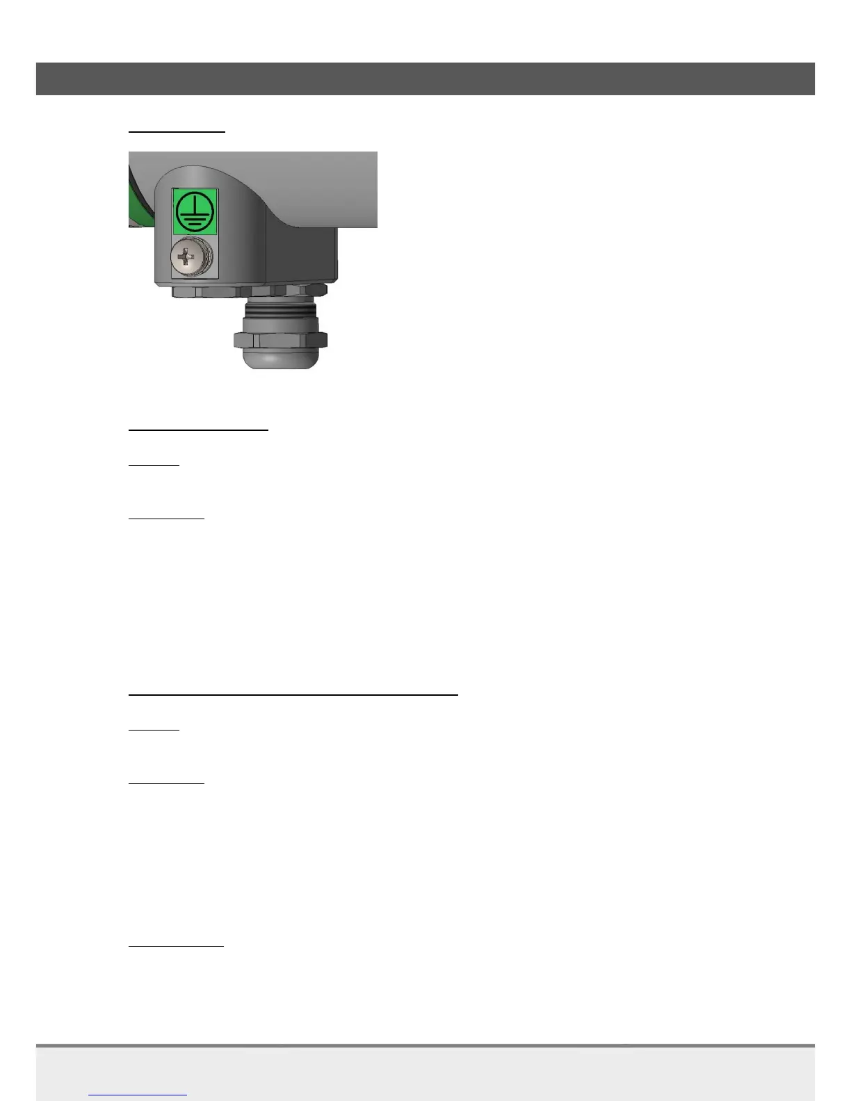
Protective Earth connect safety ground >= 4 mm
2
to housing PE post
PE post
Power Cable and Gland
Included
Cable gland 3 – 7 mm [cable outer diameter]
Not included
2 Wire Cable + , - [24V nominal]
o Conductor cross section 0.5 . . 2.5 mm² [flexible wire, with plastic sleeved ferrule]
o Length [preferred] <= 10m [@ 0.50 mm² / 20 AWG]
o Length [3% cable losses] 33 m [@ 0,50 mm² / 20 AWG]
49 m [@ 0,75 mm² / 18 AWG]
66 m [@ 1,0 mm² / 17 AWG]
98 m [@ 1,5 mm² / 15 AWG]
164 m [@ 2,5 mm² / 13 AWG]
HART data, with 4-20 mA Output, data cable and Gland
Included
Cable gland 3 - 10 mm [cable outer diameter]
Not included
Load resistance 50 to 1000 Ω [250 Ω nominal cable resistance included]
Minimum conductor size 0.51 mm / 24AWG [runs less than 1500 m]
Minimum conductor size 0.81 mm / 20AWG [for longer distance]
Maximum cable length: 2700m [Cap < 70 pF/m]
Cable type twisted single pair shielded, or multiple pair with overall shield
[Cap <= 65 pF/m]
Shield connection use grounding at one point only, at the host or DCS system
Cable examples:
Lapp Cable: 2170220 Unitronic BUS L2/FIP
Size = 0.64 mm (22AWG), OD = 7.8 mm, Cap = 30 pF/m, Loop_DCR = 115 Ω/km
Belden: 3079E DataBus ISA/SP-50
Size = 0.64 mm (22AWG), OD = 8.0 mm, Cap = 28 pF/m, Loop_DCR = 106 Ω/km