PERFORMER Digital Partyline, User Manual, Version 2.30
4.3.2 SUB D 15 Connector ..........................................................................................................................................27
4.3.3 PGM IN Connector.............................................................................................................................................. 28
4.3.4 SA OUT Connector .............................................................................................................................................. 28
4.3.5 Upstream Connector .......................................................................................................................................... 28
4.3.6 Downstream Connector ..................................................................................................................................... 29
4.3.7 Headset XLR Connector..................................................................................................................................... 29
4.3.8 DIP Switch CD-2.................................................................................................................................................. 30
4.4 Specifications.................................................................................................................................................................... 31
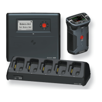
5 PERFORMER C3 DIGITAL BELTPACK 32
5.1 Get Started ........................................................................................................................................................................ 32
5.2 User Elements Top............................................................................................................................................................ 32
5.2.1 Error LED (red).................................................................................................................................................... 32
5.2.2 CALL LED (orange) ............................................................................................................................................. 33
5.2.3 Channel A/B LED (green) .................................................................................................................................. 33
5.2.4 Power LED........................................................................................................................................................... 33
5.2.5 Channel Knob (2 Functions)..............................................................................................................................33
5.2.6 CALL Key .............................................................................................................................................................34
5.2.7 GPI Key (Formerly SCALL).................................................................................................................................. 34
5.3 User Elements Bottom .....................................................................................................................................................34
5.3.1 Headset Connector ............................................................................................................................................34
5.3.2 DIP Switch Functions .........................................................................................................................................35
5.3.3 Upstream............................................................................................................................................................. 35
5.3.4 Downstream........................................................................................................................................................ 35
5.4 Specifications.................................................................................................................................................................... 36
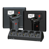
6 PERFORMER CW-2 WALL MOUNT SPK / HS STATION 37
6.1 Get Started ........................................................................................................................................................................ 37
6.2 User Elements Front .........................................................................................................................................................37
6.2.1 Channel Knob (2 Functions)..............................................................................................................................38
6.2.2 CALL Key .............................................................................................................................................................38
6.2.3 GPI Key (Formerly SCALL).................................................................................................................................. 38
6.2.4 Side Tone Key (momentary) .............................................................................................................................. 38
6.2.5 HS Key (momentary) ..........................................................................................................................................39
6.2.6 Microphone Connector ......................................................................................................................................39
6.2.7 Headset Connector ............................................................................................................................................39
6.2.8 Error LED (red).................................................................................................................................................... 39
6.2.9 CALL LED (orange) ............................................................................................................................................. 40
6.2.10 Channel A/B LED (green) .................................................................................................................................. 40
6.2.11 Power LED........................................................................................................................................................... 40
6.2.12 HS LED (green) / Speaker LED (red) ................................................................................................................41
6.2.13 DIP Switch CW-2 .................................................................................................................................................42
6.3 The Multi-Pin Connector ...................................................................................................................................................43
6.3.1 J100 / J101 Connector Pin Out ........................................................................................................................ 43
6.3.2 Connection to 3-pole XLR cable........................................................................................................................44
6.3.3 Downstream Analogue Input............................................................................................................................. 45
6.4 Specifications.................................................................................................................................................................... 45
7 PERFORMER C31 SPLIT BOX 47
7.1 User Elements “Upstream“ .............................................................................................................................................. 47
7.1.1 DATA LED ............................................................................................................................................................ 47
7.1.2 Power LED........................................................................................................................................................... 48
7.1.3 Pin Out DC ext. 48V ............................................................................................................................................48
7.2 User Elements “Downstream” ......................................................................................................................................... 48
7.3 Specifications.................................................................................................................................................................... 49
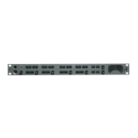
8 PERFORMER C44 / C44PLUS SYSTEM INTERFACE 50
8.1.1 Get Started.......................................................................................................................................................... 50
8.1.2 Basic Configuration ............................................................................................................................................ 51
8.2 User Elements Front .........................................................................................................................................................51
8.2.1 LEDs..................................................................................................................................................................... 51
8.2.2 3-pole XLR Connectors ......................................................................................................................................51
8.2.3 Analog Connections ...........................................................................................................................................51
Page 4