2.5.2 Cable
When wiring loadcells use only high quality shielded multi-core cable. The cable should be run as far away
from any other cabling as possible (minimum separation distance 150mm). Do not bundle loadcell cables with
power or control switching cables as interference can trigger display instability, and cause unreliable operation.
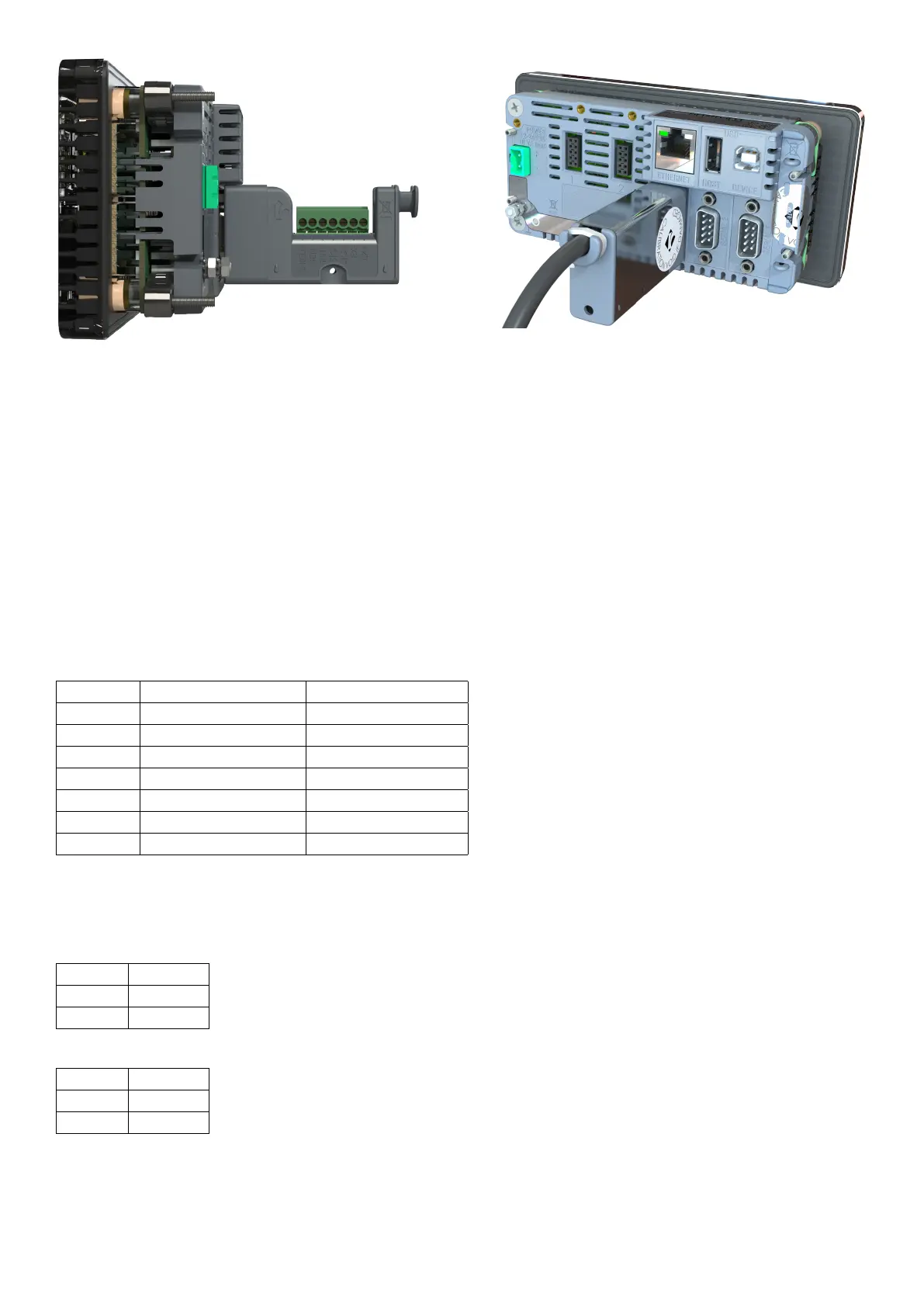
The loadcell shield must be installed so as to connect electrically with the metal shell of the DB9 plug or screw
terminal shield connection in order for the C500 series to provide its full EMC resistance. Any noise absorbed
by the cable shield must be conducted as quickly as possible to the indicator case via the DB9 plug shell,
then direct to a solid earthing point via the earth terminal in the power input socket (or earthing lug on DC
models).
2.5.3 Six Wire Connection
The connection is made using a standard DB9 male plug. The loadcell socket is wired for six wire systems as
follows:
DB9 Pin Screw Terminal Pin Function
1 1 Positive excitation
2 5 Positive sense
3 2 Negative excitation
4 6 Negative sense
9 3 Positive signal
8 4 Negative signal
Shell 7 Cable shield
2.5.4 Four Wire Connection
When a four wire loadcell system is connected some solder or wire bridges are used to ensure that the excitation
voltages are fed into the sense inputs. For DB9 connections, short the following:
EX pin Short to
1 2
3 4
For screw terminal connections, short the following:
EX pin Short to
1 5
2 6
2.6 EX-I Loadcell Connection
The C500 series can be installed with barriers for EX-i applications. Six-wire connection is necessary in this
case to achieve an acceptable performance. The C500 series is not intrinsic safe and must be installed outside
the hazardous area. Connections for an EX-I application are:
6 C500-600-2.0.3