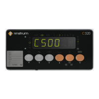
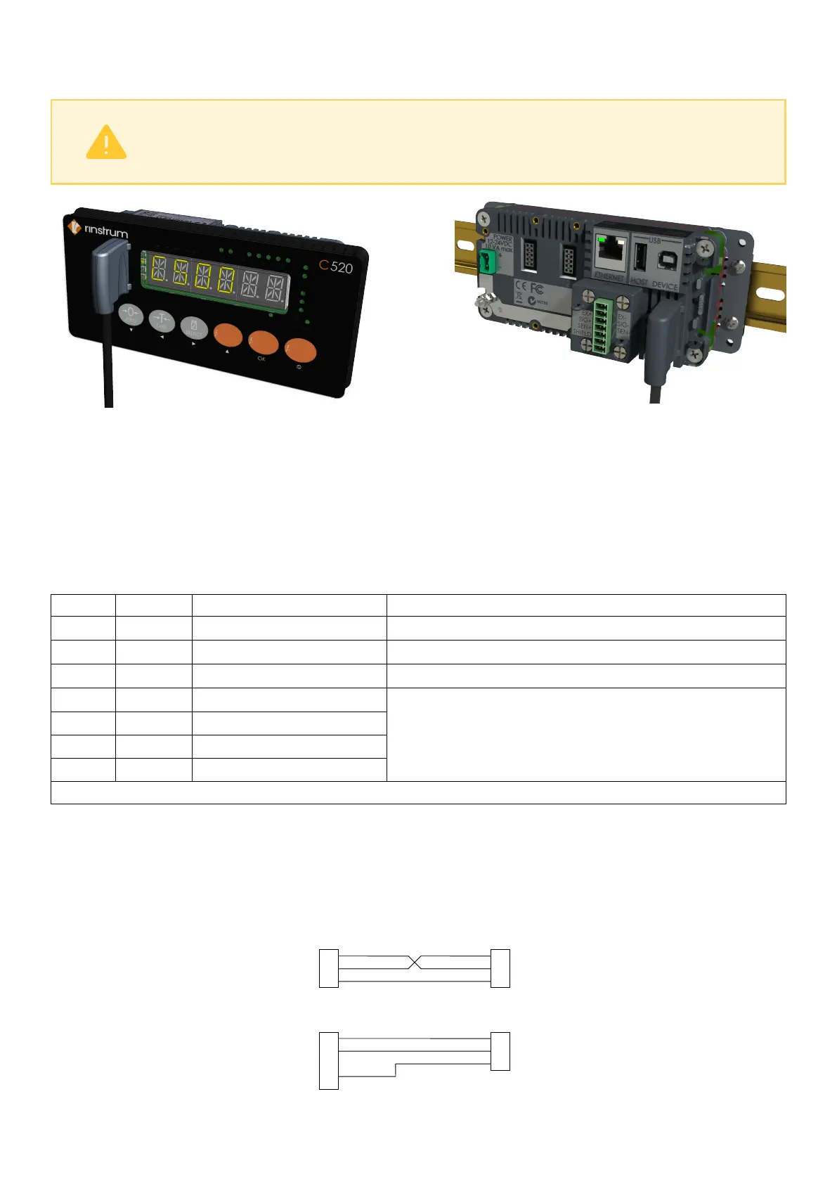
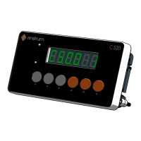
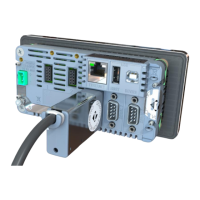
The PC end of the cable is a standard USB connector. The instrument end of the cable attaches to the left
side of the indicator display, or the rear of the indicator as shown below.
Warning!
The optical coupling head contains a strong magnet and should not be placed near
any magnetic storage media (eg. credit cards, floppy disks etc.)
2.8 DB9 Serial Port 1 Connection (C520 Only)
2.8.1 Overview
This port has two types of output drivers: RS232 and RS422/RS485. It is generally used for connecting
external computers or PLCs, or as a driver for remote displays. External devices can be connected as either
RS232 or RS422/485 (4 wire). All connections for the port are on the Serial 1 connector. This is a standard
DB9 socket requiring a female DB9 plug. Since both RS232 and RS422/485 are connected in parallel within
the C520, they will both output exactly the same message. The connections for the outputs are shown below.
Pin No Function Description Connect to external device
2 RX1 RS232 receive Transmit (DB9 pin 3)
3 TX1 RS232 transmit Receive (DB9 pin 2)
5 GND1 RS232 ground Ground (DB9 pin 5)
6 RA RS422/RS485 receive A-
If RS232 is used, do not connect pins 6..9. A
null-modem cable is not suitable. These pins
are connected internally to serial port 2.
7 RB RS422/RS485 receive B+
8 TA RS422/RS485 transmit A-
9 TB RS422/RS485 transmit B-
Shield: Connect as directly as possible to the metal DB9 shell.
2.8.2 RS422/RS485 Termination Resistors
The termination resistors required by RS422 or RS485 networks are built into the C520. The resistors are used
to terminate the ends of the network to provide a balanced loading. See Section 5.5.
2.8.3 RS232 Connection To A PC
8 C500-600-2.0.3