15 Accessory Modules
15.1 Introduction
The indicator can be expanded by the installation of optional accessory modules. A range of modules are
available:
M5401 Analogue output module
M5301 8 I/O module
M5101 AC power module
M5201 RS232 full duplex / RS232 transmit only serial communications module
M5203 RS485 full duplex / RS485 transmit only serial communications module
Two modules can be installed on the indicator.
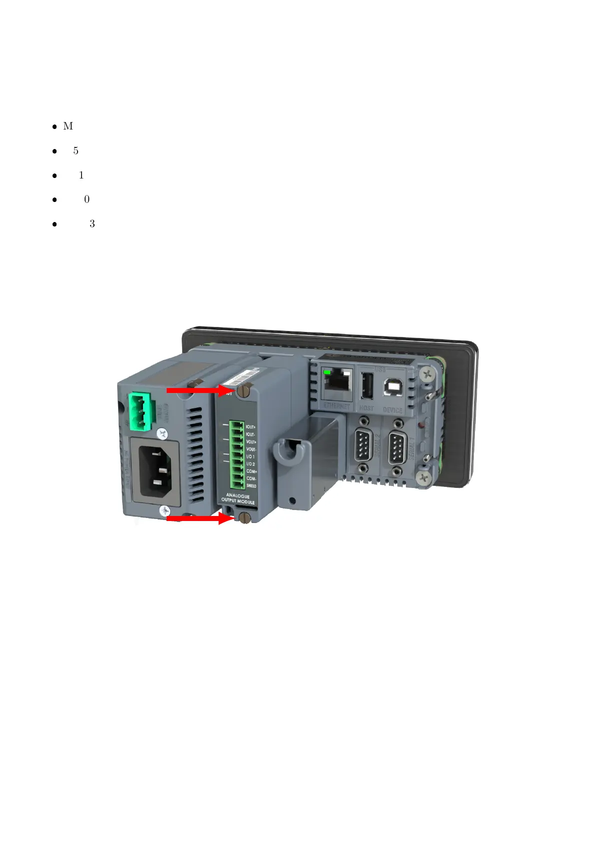
15.2 Installation
Isolate the indicator from the power before installing any module. Each module is installed onto the back panel
of the indicator as shown below.
15.3 Mapping
Serial modules are mapped according to their physical location on the rear of the indicator. The module in
slot 1 maps to SER.M.1A / SER.M.1B. The module in slot 2 maps to SER.M.2A / SER.M.2B.
15.4 Configuration
Modules are configured using the indicator setup menus. See Sections 5.5, 5.6, 5.9 and 5.10
15.5 Details
See the datasheet for your module.
64 C500-600-2.0.3