2.5 Loadcell Connection
2.5.1 Overview
The C500 series can drive any number of full bridge strain gauge loadcells up to the equivalent of 16 x 350
ohm cells (21 ohm load).
The span range of the loadcell outputs (the change of signal from the loadcells between zero load and full gross
load) must be within the range of 0.2 to 5.0 mV/V. Very low output scale bases can be used with the C500
series, but may induce some instability in the weight readings when used with higher resolutions. Generally
speaking, the higher the output, or the lower the number of divisions, the greater the display stability and
accuracy.
When shunting loadcells, use only good quality metal film resisters with high temperature stability ratings.
Typical values for zero adjustment would fall within the range of 500k ohms (small effect) to 50k ohms (larger
effect).
The C500 series has a mV/V meter test mode which can be used to check scale base signal output levels. Refer
to Section 5.8.
Warning!
Sense lines must be connected. Failure to do this will result in the C500 series
displaying an error message (E00040, E00080 or E000C0).
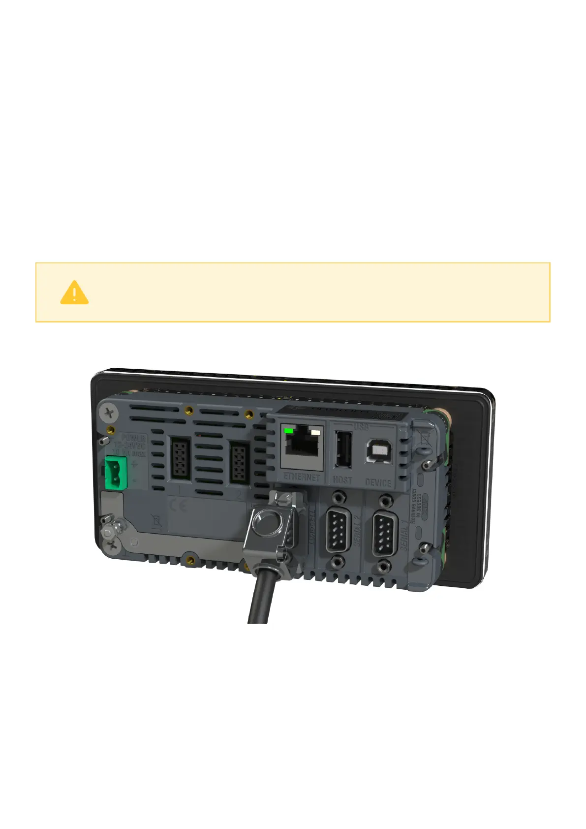
The C500 series offers two loadcell connection options. For replacement of 5000 indicators, the DB9 connection
can be used, as shown below:
For new installations, the loadcell adaptor can be attached to the rear of the indicator. This permits easier
connection of the loadcell using screw terminals.
5 C500-600-2.0.3