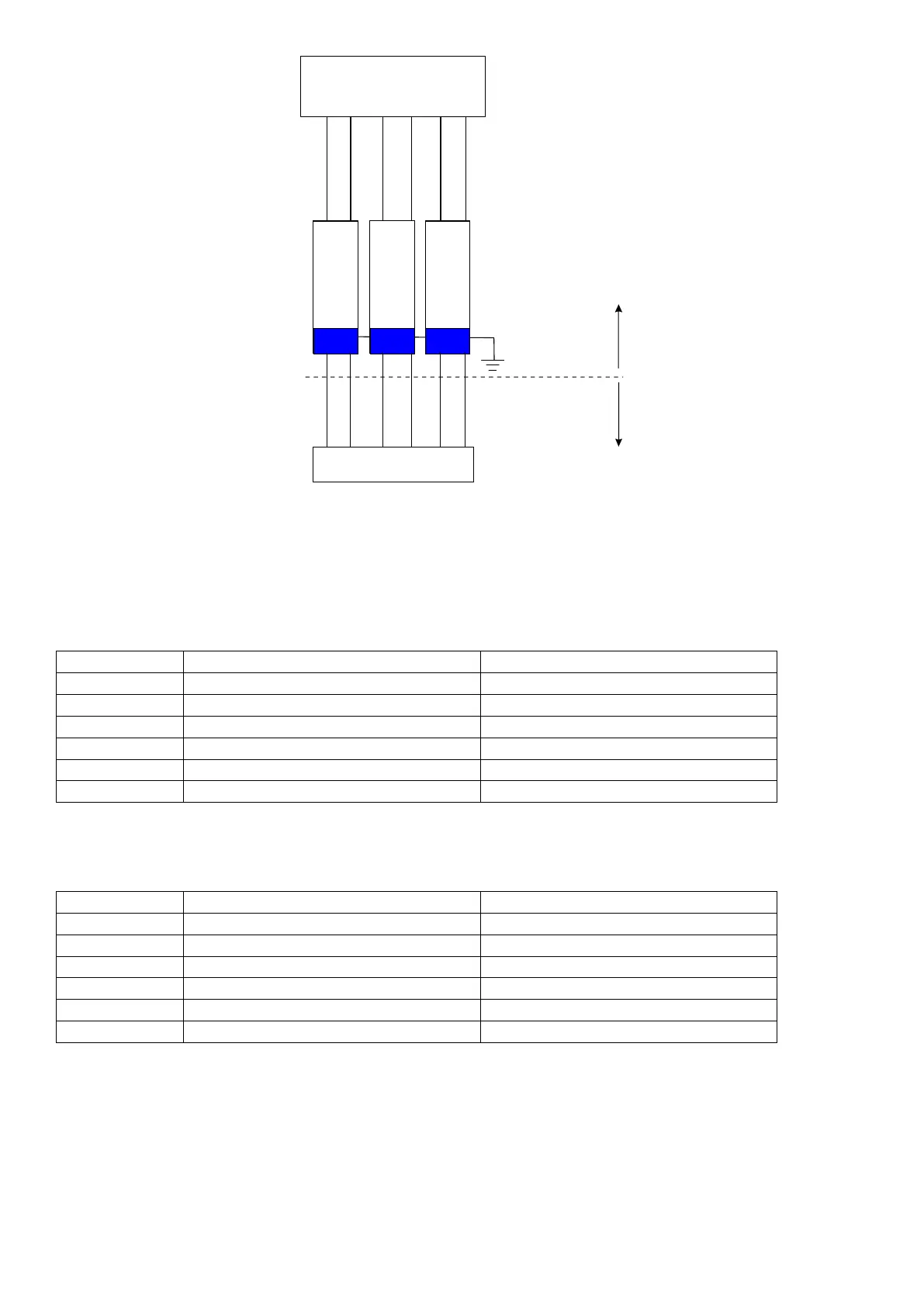
SD01
EX-Area
(Zone 1,2)
Non-EX-
Area
UN = 6,3 eff. V
Ri = 317 Ohm
UN = 6,3 eff. V
Ri = 3017 Ohm
UN = 1 eff. V
Ri = 310 Ohm
Excitation +
Excitation +
Sense +
Sense +
Signal -
Signal -
Signal +
Signal +
Sense -
Sense -
Excitation -
Excitation -
C520 or C530
Scale
If errors E00040, E00080 or E000C0 occur in an EX-I application the check of the voltage drop over the sense
lines can be turned off with the OPTION:SENS.CH setting. Thus the C500 series will accept a higher voltage
drop over the sense lines, but will no longer detect problems with the sense connections.
2.6.1 Non-trade Limits
C520/C530 with zener barrier SD01 (Input signal ≥ 0,2 µV/e, divisions 3000d, loadcells 2mV/V)
No of loadcells Minimum yield of the loadcells 350 Ω Minimum yield of the loadcells 700 Ω
1 7 % 6 %
2 11 % 7 %
3 14 % 9 %
4 17 % 11 %
6 24 % 14 %
8 31 % 18 %
2.6.2 Trade Limits
C520/C530 with zener barrier SD01 (Input signal ≥ 1,0 µV/e, divisions 3000d, loadcells 2mV/V)
No of loadcells Minimum yield of the loadcells 350 Ω Minimum yield of the loadcells 700 Ω
1 36 % 28 %
2 53 % 36 %
3 70 % 45 %
4 87 % 53 %
6 - 70 %
8 - 87 %
The minimum yield of the loadcells is proportional to the divisions. E.g. at 2000d and 4 loadcells 350 ohm the
minimum yield is 58%. These calculations are valid for an overall maximum cable resistance of 3.5 ohm per
lead. Larger cable resistances increase the minimum yield.
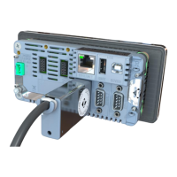
2.7 Optical Communications
A temporary infrared communications link can be established between the instrument and a PC using an
optional cable. This connection can be used to transfer setup and calibration information from a PC.
7 C500-600-2.0.3