2F-85 & 2F-140 - Instruction Manual
Preset 1 Preset 2 Preset 3 Preset 4
Position 100 0 100 0
Speed 100 100 0 0
Force 100 100 1* 1*
*To preserve object lost detection, force isnot set to 0.
Table 3-3: Factory presets for 2F-85 & 2F-140 Grippers
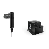
Installing the I/O Coupling
Mounting the I/O Coupling
1. Insert the provided dowel pin into the tool flange.
2. Mount the I/O Coupling on the robot tool flange. Align it properly with the dowel pin.
3. Use the provided M6 screws, the M6 tooth lock washers, and the 4mm hex key to secure the I/O Coupling.
Mounting the Gripper onto the I/O Coupling
1. Fasten the gripper onto the I/O Coupling using the M5 screws and tooth lock washers of the gripper.
Caution
Be careful with the fragile pins while installing the gripper onto the I/O Coupling. Any abrupt movement can damage
the pinsand lead to product malfunction.
2. Plug the I/O Coupling connector into the robot tool flange connector.
Caution
Make sure to close the silicone door of the I/O coupling micro-USB port to prevent any dust or liquid infiltration.
3. Make sure the voltage is set at 24V to operate the gripper:
i. Select the I/O Tab.
ii. On the bottom right corner of the page, select Robotiq_Wrist_Connectionin the Controlled by drop down menu.
iii. Make sure to save in the Installation Tab.
25