2F-85 & 2F-140 - Instruction Manual
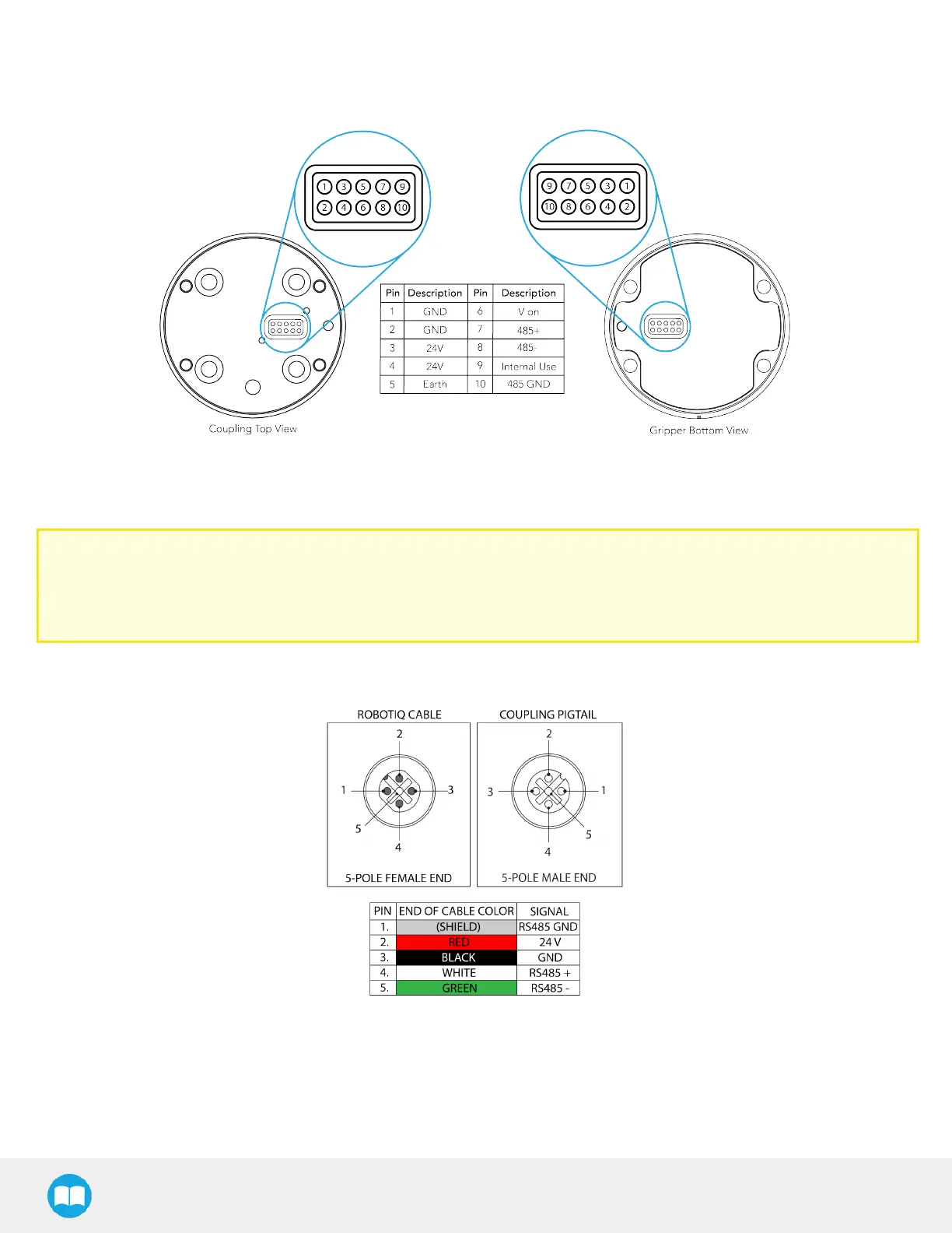
3.5.2. Pinout Interface
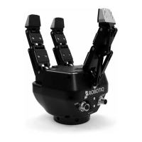
The gripper interfaces with its coupling via a 10-spring pin connector located on itsouter surface.
Fig. 3-11: Pinout of the 2F-85 & 2F-140 Gripper cable-to-wrist coupling
3.5.3.Coupling to Controller
Caution
Use proper cabling management. Make sure to leave enough slack in the cabling to allow movement of the gripper
along all axeswithout pulling out the connectors. Always protect the controller-side (robot side) connector of the cable
with a strain relief cable clamp.
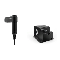
The figure below illustratesthe 2-Finger pigtail connector from the coupling (GRP-CPL-062 orAGC-CPL-XXX-002), the device
cable on the robot side (CBL-COM-2065-XX) and their associated pinout.
Fig. 3-12: Pinout of the 2-Finger pigtail and device cable.
32