Roche Diagnostics
Operator’s Manual · Version 3.1 E-61
Cedex Bio System 14 ISE maintenance
ISE maintenance actions
a To install the new ISE unit tubing
1
Remove the new tubing set from its packaging.
2
Place the tubing roughly in position on the ISE unit. Refer to the illustration on
the ISE tubing set cover.
Take care not to cut the tubing, avoid any sharp objects.
3
Press the tubes into their routing.
Take care not to compress the tubes or to kink them.
Make sure to press the tubing firmly in its routing around the ISE Reference
Solution sensor.
4
Connect the tubing to the ISE tower and then install the tower.
5
After connecting the tubing to the electrode block, make sure the electrodes are
properly mounted when closing the tension lever. Close the electrode block cover.
6
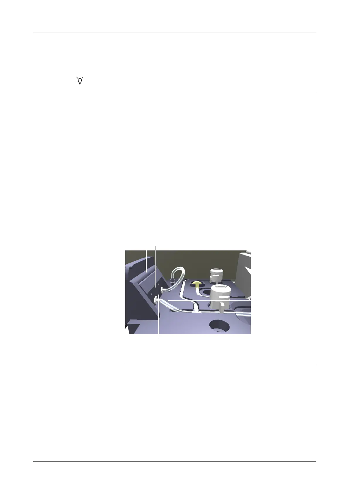
When connecting the tubing to the peristaltic pump connector block, take care
not to introduce sharp angles in the tubing. (Sharp angles may lead to flow
problems.)
Always insert the tubing connectors in the lower set of holes in the pump
connector block, and make sure to fully insert the tubing in the connectors.
7
Install all clamps and pinch valve caps. Be sure to place the clamps in the correct
position, covering the tubing.
8
Install the lid of the fluid distributor.
Make sure to keep the piece of tubing designed to fit at the underside of the mixing
tower. It will be required when a service representative performs periodic maintenance.
A Peristaltic pump block
B Upper set of sockets.
C There are no sharp angles in the tubing.
D Lower set of sockets.
Figure E-16
 Loading...